Flux barriers in tooth region fo SL 12N14P

Cohesive

User gesperrt
Hi,
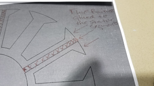
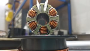
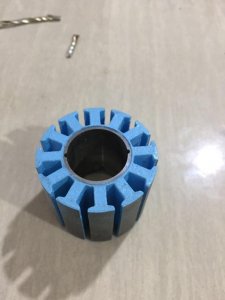
I've been looking at areas of improvement for the HKIII series of scorpion stators. The first thing I note is that a single layer wind has a higher wind factor of about 3.3% than a dual layer but it suffers a lot of iron loss due to it's amplification of the fundamental. It is known that a novel way to minimize these losses are with the use of flux barriers. Information from Gurakuq Dajaku, and Dieter Gerling's study into this topic yielded the result that with a 12 slot 14 pole FSCW, a single layer sees more improvement than a dual layer from the use of flux barriers. They studied two types of barriers. Ones in the yolk region and ones in the tooth region. It was found that with a dual layer if the yolk was cut away every other slot by 65% this eliminated totally the fundamental but it also slightly reduced the 5th and 7th. Better but not the best. It was found with a single layer at 95% yolk cut away a reduction of 60% bringing the first to 9.03% just 2.3% higher than a conventional dual layer for this topology, while actually increasing the 5th and 7th. making it more efficient and raising it's torque output. The problem with yolk cutouts on these stators is they have a fairly thin yolk. The 4035 for instance has only about 1.5mm thickness so at .95% cut away you'd only have at the thinnest parts .75mm of yolk thickness. This may work but it seem like it would make an awfully fragile stator. Plus since it is a post facto design idea I don't know it the yolk was purposely designed thin here to purposely effect the flux distribution. Finally we come to the point of tooth flux barriers where the stator is basically segmented into 4 quarters of 2x 1/3 teeth with one full tooth in the middle with the flux barriers making up the middle third between each quarter stator segment. Doing this in a single layer showed significant reduction in the first and fifth harmonic with a significant increase in the 7th. the working harmonic for a 14 pole motor. Problem here is in the test they did a IPM and were doing EPM. That makes it difficult to assemble a stator we have no case to put in. This leads me to the idea that I can possibly do sort of booth with this stator. Simply have a basically the same dimensional stator cut but only cut away the middle third of each tooth all the way down halfway into the yolks thickness and insert the barrier strips. If this worked it would be great as the single layer 14 pole motor with could show a total 60% reduction of sub harmonics and a increase in torque output up to 16%. The 14 pole single layer would also have higher induction and much better field weakening capability. The only other ideas I can come up with are to design or start with a stator with more iron...a thicker yolk. The other thing that reduces sub harmonics is Gerling winding schemes.
 

Anhänge

  • 4035 flux barrier tooth regions.png
    4035 flux barrier tooth regions.png
    172,4 KB · Aufrufe: 244

FamZim

User
Hallo

Die Schlitze in Hammerkopf und Steg reduziern zwar die Übermagnetisierung am Hammerkopf, gleichzeitig wirt aber der Steg vom Querschnitt her reduziert.
Ob sich da Vorteil und Nachteil nicht aufhebt ?
Und warum nur jeder zweite ?
Eine Verbesserung könnte Ich mir mit Schnittbandkern-Material vorstellen, die V förmig, 30 ° zu einem Stator verklebt werden.
Die sind höher magnetisierbar und das Feld läuft besser in den Kurven. )Knicken).

Gruß Aloys.
 

Cohesive

User gesperrt
Information from Gurakuq Dajaku, and Dieter Gerling's study into this topic yielded the result that with a 12 slot 14 pole FSCW, a single layer sees more improvement than a dual layer from the use of flux barriers. They studied two types of barriers. Ones in the yolk region and ones in the tooth region. It was found that with a dual layer if the yolk was cut away every other slot by 65% this eliminated totally the fundamental but it also slightly reduced the 5th and 7th. Better but not the best. It was found with a single layer at 95% yolk cut away a reduction of 60% bringing the first to 9.03% just 2.3% higher than a conventional dual layer for this topology, while actually increasing the 5th and 7th. making it more efficient and raising it's torque output. The problem with yolk cutouts on these stators is they have a fairly thin yolk. The 4035 for instance has only about 1.5mm thickness so at .95% cut away you'd only have at the thinnest parts .75mm of yolk thickness. This may work but it seem like it would make an awfully fragile stator. Plus since it is a post facto design idea I don't know it the yolk was purposely designed thin here to purposely effect the flux distribution. Finally we come to the point of tooth flux barriers where the stator is basically segmented into 4 quarters of 2x 1/3 teeth with one full tooth in the middle with the flux barriers making up the middle third between each quarter stator segment. Doing this in a single layer showed significant reduction in the first and fifth harmonic with a significant increase in the 7th. the working harmonic for a 14 pole motor. Problem here is in the test they did a IPM and were doing EPM. That makes it difficult to assemble a stator we have no case to put in. This leads me to the idea that I can possibly do sort of booth with this stator. Simply have a basically the same dimensional stator cut but only cut away the middle third of each tooth all the way down halfway into the yolks thickness and insert the barrier strips. If this worked it would be great as the single layer 14 pole motor with could show a total 60% reduction of sub harmonics and a increase in torque output up to 16%. The 14 pole single layer would also have higher induction and much better field weakening capability. The only other ideas I can come up with are to design or start with a stator with more iron...a thicker yolk. The other thing that reduces sub harmonics is Gerling winding schemes.
 

Cohesive

User gesperrt
My comparison stator is the standard HKIII 4035 wrapped with 10 turns of 1.5mm SL parallel wye wind.
 

Anhänge

  • 20180821_215040.jpg
    20180821_215040.jpg
    189,5 KB · Aufrufe: 234

Cohesive

User gesperrt
Btw this might be the next step in more torque for a pyro 1000 or anyone running 14 pole motors. With adequate iron it is the perfect candidate for this experiment. If executed correctly an increase in torque up to 16% and better efficiency is possible according to the lab results of DG and GD.

~Analysis Of Different PM Machines with Concentrated Windings and Flux Barriers in the Stator Core. By Dajaku and Gerling~
 

Anhänge

  • IMG_7879.jpg
    IMG_7879.jpg
    32,1 KB · Aufrufe: 262
Hallo Cohesive

my first think; can only be better for verry low-flux.

but for high-flux, can make it problems?(for Star)
4035 flux barrier tooth regions.png


Classic
:4035 flux barrier tooth regions1.png
 

Cohesive

User gesperrt
Hi Holger,
I sent you pm about Tanto some time ago do you remember?:)

Anyway If you want I have diagram that shows what flux linkage looks like when it is forced down each outside 1/3rds of the teeth. The linkage becomes much more symmetrical with respect to the physical topology. From my understanding this help to get rid of modal vibrations of a low order. Reduces torque ripple and because we move from 10 to 14 poles we have a lower n spec and can therefore also use shorter larger conductor for the same Kv.


3 bullets in Gerling/Dajaku's conclusions of their findings.

Sub harmonic reduction of more than 60%
Torque density improvement ESPECIALLY for the 12 tooth 14 pole design with the SL winding The new technique show a 16% increase in torque.
High field weakening capability. Flux barriers reduce the winding harmonic inductances. For the SL winding type, the new stator improves the field weakening capability of the machine.

May I suggest you read fully the IEEE fellow's paper before you make or I address your conclusions.
 
Hallo Cohesive
Yes i remember, but i dont know what is with the tantow now.

Were can in find this paper ?

i think the tooth with winding must be smaler, same width as the both small tooth with the barriers together ?!?(for no need a full barrier)
4035 flux barrier tooth regions2.png
 
I have find the paper. afer short reading (time....) i have seen, they make this:
4035 flux barrier tooth regions2.png

But this can be an problem in practice:
4035 flux barrier tooth regions.png
 

Cohesive

User gesperrt
Holger,
For this motor maybe the number should be different :confused: But this "1/3" total tooth width number is where they found through testing the documented improvement and so we start there with our test. Do you have any suggestions?
 

Cohesive

User gesperrt
If you actually read my first post you may find in it..... a discussion about the mechanical integrity of the stator in an outrunner configuration versus an inrunner and why I landed here and felt this is a testable hybrid option for a mechanically stable outrunner stator which will make unnecessary all our conjecture and speculation when complete.

In your perfect designed stator you now have the issue of how to solidly attach it to the bearing tube and it not come apart or alter the air gap at the amazing forces we would put upon it. In building the stack for it what practical solution have you conceived for this MINOR problem?

Obviously the flux barrier creates infinite resistance so we only try to raise resitance it as much as we can in that area without a full cutout losing all mechanical integrity but we also are into the yolk and hope it chooses another path to flow.
 

Cohesive

User gesperrt
So here you go...... maybe a dovetail grove locking detail will work to adjoin the flux barrier to the stator segments.
 

Anhänge

  • 20180822_192503.png
    20180822_192503.png
    344,5 KB · Aufrufe: 244

Cohesive

User gesperrt
Finished control motor.
 

Anhänge

  • 20180822_000716.jpg
    20180822_000716.jpg
    125,4 KB · Aufrufe: 231
  • 20180822_000642.png
    20180822_000642.png
    609,6 KB · Aufrufe: 245

Cohesive

User gesperrt
The assembly will require 6 segments be stacked. The segments will be joined at the flux barriers. I wait for the quote on laser cutting the prototype. We think we can secure the segments with adhesive and carbon string. For a fair comparison we start with general silicon steel at .35mm thickness like scorpion advertises they use on larger motors.

flux barrier assembly .png
 

Anhänge

  • dg stator.png
    dg stator.png
    69,2 KB · Aufrufe: 261

Cohesive

User gesperrt
As a side note we also wait for quote on true 12N14P SPS outrunner stator derived from original inrunner patent information.
 

Anhänge

  • 12N14P SPS1.png
    12N14P SPS1.png
    109,1 KB · Aufrufe: 283

FamZim

User
Hallo

Carbon würde ich nicht nehmen , da es sehr gut leitent ist. (Kurzschlußwicklung).
Ich würde eine GFK Endscheibe nehmen ohne Schlitze.
Darauf ~10 mm dick die 6 Segmente.
Dann wieder eine GFK Scheibe und wieder ~ 10 mm dick die 6 Segmente usw .
Zum Schluß wieder eine GFK Endscheibe.

Beim SPS Blechpaket halte ich den Eisenquerschnitt für Überdimensioniert, es ist zu wenig Wickelraum für CU!
50 zu 50 % ist ein guter Mittelweg.

Gruß Aloys.
 

Cohesive

User gesperrt
The translation to English doesn't fully make sense. I have also not given any numbers for the sps coils slot depths or widths so a very good assessment without the essential information. The original doesn't look much different . Can I see calculations that show a 50 50 mix of copper and iron ideal in existing cored motors that perform well. Id venture to say most cored motors have more iron than copper or vice versa but not equal. When there is little iron the induction goes low and your fet drivers have to be able to accommodate the necessary clock speed to run correctly. If I weigh the cored motors off the shelf Id be surprised the results would not support this thinking of typically more iron than copper. Maybe I'm wrong. But besides this is prototype for testing to find what's best and I'm always willing to look at other successful attempts that were done right but they are few and far between from my view so far. Hopefully you can change this and will post what it should look like when its done right. From this we can all learn something.
 

FamZim

User
Ja mit Übersetzer ist das schon ein Abenteuer, habe ich eben erstmalig gemacht.

Die 50 - 50 % gelten nur "für den Wickelraum und die Stege", um die die Windungen gewickelt sind, nicht das ganze Eisen der Maschine.
Da ist beim 12 Nutschnitt deutlich mehr Platz für CU als Eisen.
Die 50 % kommen aus der Logig das ein Motor ohne CU, aber nur Eisen keine Elektrische Energie einleiten kann, und eine Maschine mit nur CU kaum ein Magnetfelt aufbauen kann, was durch Eisen verstärkt wirt.
Also wirt der Raum geteilt in 2 Teilmengen.

Die Schlitze im Stator werden das seitliche Feldwandern nicht wie gehofft fast unmöglich machen, sondern nur schwächen.
Sehe mal die Fläche und der Abstand (Luftspallt) zu den Magneten.
Vergleiche das dann mit den wesendlich grösseren Flächen an den Schlitzen, und dessen "Luftspallt".
Man kann aber statt Iso ein CU Blech in den Schlitz kleben, das dann eine Aktive Sperre gegen Magnetfluss ist.
Alle Teilsegmente "könnte" man mit einer GFK Wickel um den Stator zusammenhalten.
Die Wicklung müste dann durchgefädelt werden.

Gruß Aloys.
 
Ansicht hell / dunkel umschalten
Oben Unten