FSCW 36N28P induction motor.

Cohesive

User gesperrt
Hi,
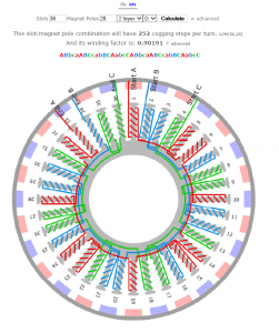
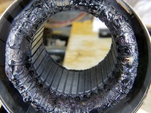
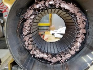
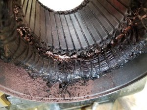
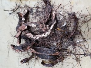
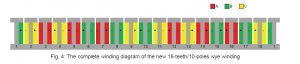
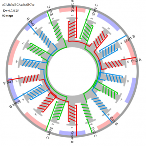
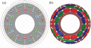
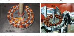
Most motor guys know the value of concentrated coils in motor construction. Most also know the downsides. There is relief that Dr. Dieter Gerling has created a semi distributed coil system for FSCW inductions machines and increase the performance dramatically. We have choices here. Do we leave it an induction machine or should we make it a large BLDC machine? I have one here out of the trash that was burned so I figured this might be a good time to experience experiment on this topic. I cleaned the rotor and body and decided why not try. Ill have to re-find the paper on this and post it but I was wondering are there any other cool ideas I overlooked?

Thanks
Hubert.
 

Anhänge

  • 20181204_193040.jpg
    20181204_193040.jpg
    237 KB · Aufrufe: 137
  • induction wind.png
    induction wind.png
    530,3 KB · Aufrufe: 193
  • 20181204_193045.jpg
    20181204_193045.jpg
    220,3 KB · Aufrufe: 112
  • 20181204_223507.jpg
    20181204_223507.jpg
    243,7 KB · Aufrufe: 151

Cohesive

User gesperrt
.... Respirators and eye protection are a must.
 

Anhänge

  • 20181205_002250.jpg
    20181205_002250.jpg
    140,6 KB · Aufrufe: 143
  • 20181205_001613.jpg
    20181205_001613.jpg
    137,1 KB · Aufrufe: 114
  • 20181205_004620.jpg
    20181205_004620.jpg
    178,2 KB · Aufrufe: 106

FamZim

User
Hallo

Warum eine so schwierige Wicklung ? ja klaar geht auch.
Aber 30 - 32 - 34 - oder 38 Pole sind doch einfacher !

Gruß Aloys.
 

Cohesive

User gesperrt
From the induction rotor 28 is what lm left with. The higher pole give back a better Kw but I don't see them as any easier in a FSCW. Wiring it to be a dual voltage motor is truly appropriate . So a delta and a wye based on the 9 point box terminations but if I cannot do this it will be okay. If you have suggestions feel free. This is the first time I attempt an induction machine. I'd to gain the valuable experience and increase my value as a motor technician.

Thanks Aloys
 

Cohesive

User gesperrt
attachmentNew.php

Approximately 108 strands of .54 mm in the slot. (58.32mm^2)

attachmentNew.php

The significant extra weight and loss of the distributed end turns.

attachmentNew.php

Aloys,
This could be turned into a ISCAD design simply by cutting a copper lamination and soldering conductor strands like these in the slot to it on one end of the stator. The other end goes to the bipolar drive.

attachmentNew.php

More pennies from a quarter of the stator.

attachmentNew.php
 

Cohesive

User gesperrt
Before
attachmentNew.php


After
attachmentNew.php


@ Christian or Aloys
I can use the 410 nomex paper but id rather have the real slot liners. Do either of you know where I can get them in inappropriate amount? I don't want to pay 1000.00 usd for a lot purchase when I doubt Ill do this a lot. About the windings. I was thinking along these lines for a 36N28P or parallel 18N14P's

https://pdfs.semanticscholar.org/7cea/fff375460b9ca70252d405d9728931dc3d26.pdf

Here is the conventional YY variant .
 

Anhänge

  • YY 36N28P.png
    YY 36N28P.png
    849,1 KB · Aufrufe: 160

FamZim

User
Hallo

Ich kenne den Durchmesser und die Länge ja nicht, es scheint aber sehr gross zu sein.
Meiner Einschätzung nach wirt DER eine kv von 10 bis 20 haben, pro 1 V , also sehr langsam drehen.
Das ist doch meist gar nicht gewünscht, also macht man viele Parallelmotoren um die Drehzahl zu erhöhen und für einen höheren Strom.
Mit dicken Kabeln reichen dann trotzdem noch 2 oder 3 Windungen pro Steg.
Mit 30 Polen können 6 parallele geschaltet werden !

Gruß Aloys.
 

Cohesive

User gesperrt
So you estimate Kv to be between 4800 and 9600 rpm because the line power here is 480V . I doubt its 9600 rpm. 4800 sound a bit more reasonable. I wasn't necessarily trying to rewind it for our voltages because that would prevent me from using an industry VFD to test it as they are on an AC buss. If I attempted to rewind it the same . I could set the vfd's at a low amperage setting and let the new vs the old motor arm wrestle for a quick analysis of improvement. Maybe I wont do any of it and wind it like you say but It would really be nice to do one of these semi concentrated overlap proposed by Dieter that seems to be making great strides in induction and bldc machines. For refrence what is the distributed layout for a machine like this?


Ps
I received your email and and humbled by the offer and generosity. The extension of kindness does not go unnoticed. Thank you very much.
The stack length is 90 mm the slots are approximately 15mm deep.
 

Cohesive

User gesperrt
endring arrangement for 18N10P.pngAnhang anzeigen 2055878simplified gerling.pngend rind arrange ment for 18N10P new G-wye induction winding.pngAs I read the paper I realize that a Gerling single coil winding system is made easier with a contact pcb similar to what a torqstar would use. The attachment are are courtesy of:

New Cost Effective Concentrated Winding Topolology for Induction Machines
Oleg Moros, Jan Richnow, Dieter Gerling
FEAAM GmbH, University of Federal Defense Munich

ANSYS Conference &
32nd CADFEM Users’ Meeting 2014
June 4-6, 2014 – NCC Ost, Messe Nürnberg
 

Anhänge

  • IMG_0739.JPG
    IMG_0739.JPG
    96,4 KB · Aufrufe: 102

Cohesive

User gesperrt
And so we look deeper and derive a wick schema from the 18N10P new gerling WYE wind topology. Here it is aCABabcBCAcabABCbc. So if I could derive on similar for a 18N14P then we could do the part motors while maintaining the dream. If you or Chris have the solution please forward it. I'll also take a deeper look at it and fig 2's scheme. The problem is if two phases share a tooth wick is lost. So you see here the 1/3 asymmetric phase!


"This winding was presented in [3], where a remarkable advantage in efficiency compared with the 18-
teeth/10-poles model was achieved despite its lower winding factor"

~New Cost Effective Concentrated Winding Topolology for Induction Machines
Oleg Moros, Jan Richnow, Dieter Gerling
FEAAM GmbH, University of Federal Defense Munich~


Regards
Hubert
 

Anhänge

  • Winding topology for 18N10P.png
    Winding topology for 18N10P.png
    19,5 KB · Aufrufe: 96
  • Gerling Fig 3 wind 18N10P.png
    Gerling Fig 3 wind 18N10P.png
    611,9 KB · Aufrufe: 185

Cohesive

User gesperrt
Its certainly not hard to spot the point of failure when copper is fused to the tooth. But it wont happen again. From my machining back ground....If I cant run my fingers across it without feeling or getting cut by a burr its no good. Magnet wire agrees and this deburring may allow thinner slot liners.
20181206_201627.jpg
20181206_215223.jpg
 

Anhänge

  • 20181206_220306.jpg
    20181206_220306.jpg
    111,6 KB · Aufrufe: 103

Cohesive

User gesperrt
Nothing like cheap Chinese stainless silverware to make slot tools with. Maybe ill give the idea to hobby king! I can scrape slot liner from the stator and lay concentrated coils flat on the tooth with these. I can polish them more but there are no rough spots.
 

Anhänge

  • 20181207_175952.jpg
    20181207_175952.jpg
    238,1 KB · Aufrufe: 105

FamZim

User
Hallo

Die Hartlotstelle halte ich für unbedenklich, da ist ewentuell mit einem FE/CU Termoelement mal die Temperatur gemessen worden.
Die Isolationsreste sollten auf jeden Fall raus, wegen der schon angesprochenen Hohlstellen zwischen Iso und Stator.
Da kann ruhig gekratzt werden, es sollten nur keine Eisenspäne entstehen.
Die Dynamobleche haben vom Stanzen, alle eine abgerundete Kannte, wo das Stanzwerkzeug angesetzt hat, man sieht es an den blanken Rändern auf Deinen Bildern.

Gruß Aloys.
 

Cohesive

User gesperrt
Hi Aloys,

Regards
HubertI'm leaning towards a 36N28P wind with double motors terminated in a delta/wye topology similar to this. If I did 4 part motors, one in each quadrant, each one could all be a delta wye motor.
a11405037-18-simplified%20gerling.png
The 36N28P natively is relatively clean harmonically so It could possibly be a good foundation. Finalizing the wye/delta connection could be left to the end user at the box with 9 points which seems appropriate for an industrial induction machine.
 

Cohesive

User gesperrt
Hi,
Ich merke, dass die 18N10 P eine Migration war, um eine 12N10P zu verbessern und die Verschiebung zu unterbringen. Ich wusste nicht, dass ein 18N10P bereits einen niedrigen Wickelfaktor hat und es ist nicht weniger harmonisch gefüllt, dass die 18N14P, die einen Windfaktor hat, viel höher nativ. Ich frage mich, warum Gerling hier landen würde, gegen die ohnehin bessere Maschine zu verbessern?

Thanks
Hubert
 

Cohesive

User gesperrt
Hi Aloys ,

Here is a paper you may enjoy on an outer rotating FSCW induction machine and how they dealt with slot harmonics of FSCW in an induction machine. Wonder could we use big groups and auxiliary groups in the same way.

https://pdf.xuebalib.com/q205O7HqQYB.pdf
 

Anhänge

  • 4-Figure6-1.png
    4-Figure6-1.png
    259,2 KB · Aufrufe: 164
  • 4-Figure7-1.png
    4-Figure7-1.png
    310,7 KB · Aufrufe: 139

Cohesive

User gesperrt
But....
The 7th shift for 18N/14P based on Gerling/Gurakuq work I believe is....


motor 1 A-ab-BC-ca-AB-bc-C
motor 2 B-bc-CA-ab-BC-ca-A


Phases share every other tooth. If anyone see something wrong feel free to point it out but I think this is correct based on the work. since this is 18N14P we should easily be able to translate it to 36N28P and still do a wye delta combo .
 

FamZim

User
Hallo

Warum sollte man so etwas wickeln, besseres ETA ?
Das geht doch auch mit einem normalen 24 Nuter.
Jede Spule um 2 Stege statt um einen, dann sieht das genau so aus.
Nachteile sehe ich durch einen schwereren Stator und einen längeren Weg für das Magnetfeld.
Ob das dann trotzdem besser ist ??

Gruß Aloys.
 

Cohesive

User gesperrt
Ja
Wir möchten die Eta verbessern, indem wir die wenig hilfreichen Harmonischen senken, aber ich kann nicht sagen, was ohne Test sicher ist. Wir können mit einiger Sicherheit sagen, dass die FSCW-Topologie einen großen Verlust für den Induktionsrotor bedeutet
 
Ansicht hell / dunkel umschalten
Oben Unten