Du verwendest einen veralteten Browser. Es ist möglich, dass diese oder andere Websites nicht korrekt angezeigt werden.
Du solltest ein Upgrade durchführen oder einen alternativen Browser verwenden.
Du solltest ein Upgrade durchführen oder einen alternativen Browser verwenden.
Scorpion 5020 HKIII Y-D wind
- Ersteller Grands
- Erstellt am
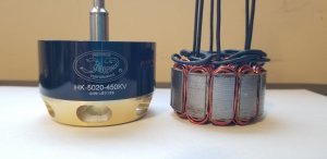

Well this spaghetti you dont eat.You see no wye bundles so It is simply is the end of the wye phases serially connected to delta phases 150 mechanical degrees away. The shifted degree between the yy and dd sinlge layer machines respective phases. Getting it easily under the hood and ensuring same legth on the phase conductors makes it wat it is. Total elimination of the 1st 11th and 13th is certainly worth it. It also boost the winding factor and lowers the pm eddies > 50%. Thec delta motor is the wyes bundle. Im sure you can clean it up with the right half parallel variants but this is a working prototype not a pretty shelf queen. The slight increase in copper loss is acceptable for the benifit it brings in reducing total losses and thermal mitigation.
The full explanation and circuit diagrams was sent direct to your email most recently Aloys. You need to check it.
The full explanation and circuit diagrams was sent direct to your email most recently Aloys. You need to check it.
Anhänge
Schaltbild wäre schön zu sehen!
frei nach google:
Nun, diese Spaghetti isst du nicht. Du siehst keine Sternbündel, also ist es einfach das Ende der Sternphasen, die seriell mit den Delta-Phasen verbunden sind und 150 mechanische Grad entfernt sind. Der Verschiebungsgrad zwischen der yy- und der dd-Einzelschicht bearbeitet die jeweiligen Phasen. Wenn Sie es einfach unter die Haube bringen und auf die gleiche Länge der Phasenleiter achten, ist es genau das Richtige für Sie. Die völlige Eliminierung des 1. 11. und 13. ist es auf jeden Fall wert. Es erhöht auch den Wicklungsfaktor und senkt die PM-Wirbel um> 50%. Der Delta-Motor ist das WYES-Bündel. Ich bin sicher, Sie können es mit der rechten Hälfte parallelen Varianten aufräumen, aber dies ist ein funktionierender Prototyp, keine hübsche Königin des Regals. Der geringfügige Anstieg des Kupferverlusts ist akzeptabel, da hierdurch die Gesamtverluste und die thermische Minderung verringert werden.
 :rolleyes:")

.png")
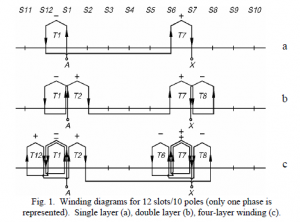
Very simple you see the short leads of each single layer delta machine terminated here. The wyes ends connects to these delta nodes. From this you attach beautiful equal length pasta which are in fact the wye machines phase ends. There are many other good multi-layer winds to improve efficiency and increase the power factor for any machine and most definitely a 12 slot 10 pole machines. 2020 is a good a time as any to evolve.

Im sure my time will be short here so you can visit my site or another forum where im allowed to inform modelers who would like to know more about the new winds and what benefits they bring.
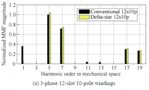
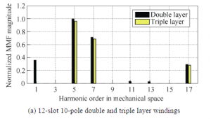
To not be confused below is the attached diagram is for winding a 3 layer 12n10p machine. So the HKIII 4035 machine is the guinea pig that comes in the new year with this. You see the relative winding harmonics attenuation with the different turns ratio between the primary and marginal coils. I'll drop the mike on this here soon enuf and head back to my 22 pole leomotions with cascaded full bridges which show a Kw of 1!
Anhänge

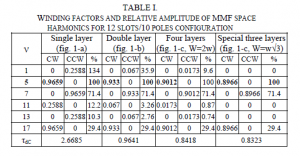
Very easy to see 3 layers compared to a DL also eliminates the 1,11,and 13th but additionally it reduces the 17th whereas just the y-d raises it about the same amount as the 3 layer reduces it. It also eliminates 19th but the winding 5th and the upper 7th is reduced slightly so ultimately you have more overall loss reduction for the cost of a bit less torque. The Kw is reduced from .93 to .90 but a machine with much lower THD is still a win as it runs much cooler with a better power factor than its primitive ancestor. Refer to the harmonic percentages chart based on turns ratio previously posted.
http://www.rc-network.de/forum/attachment.php?attachmentid=2234144&stc=1&d=1577477635
Take Care
Hubert
BTW
Christian and Aloys absorb emails so they can also help the forum with this motor stuff.
http://www.rc-network.de/forum/attachment.php?attachmentid=2234144&stc=1&d=1577477635
Take Care
Hubert
BTW
Christian and Aloys absorb emails so they can also help the forum with this motor stuff.
Anhänge
Very easy to see 3 layers compared to a DL also eliminates the 1,11,and 13th but additionally it reduces the 17th whereas just the y-d raises it about the same amount as the 3 layer reduces it. It also eliminates 19th but the winding 5th and the upper 7th is reduced slightly so ultimately you have more overall loss reduction for the cost of a bit less torque. The Kw is reduced from .93 to .90 but a machine with much lower THD is still a win as it runs much cooler with a better power factor than its primitive ancestor. Refer to the harmonic percentages chart based on turns ratio previously posted.
http://www.rc-network.de/forum/attachment.php?attachmentid=2234144&stc=1&d=1577477635
Take Care
Hubert
BTW
Christian and Aloys absorb emails so they can also help the forum with this motor stuff.
Correction: The 19th harmonic is still present with all the winds at a fairly low level it was just left out on the 2nd chart of wind comparisons. It is lower however than the conventional DL or Delta star. There is also the 4 layer 12N10P wind which brings even more fun to the machine.
Das ist niemals ein HK III!
Auf den Fotos ist eindeutig ein mindestens 7 Jahre alter HK I zu sehen. (Statorschnitt und Motorbeschriftung)
Wieviel Verluste bewirken die harmonischen Oberwellen, wenn der normal bewickelte Brushlessmotor modellbautypisch bei ca. 75% -80% seiner Leerlaufdrehzahl betrieben wird?
Danke
VG
Stefan
Auf den Fotos ist eindeutig ein mindestens 7 Jahre alter HK I zu sehen. (Statorschnitt und Motorbeschriftung)
Wieviel Verluste bewirken die harmonischen Oberwellen, wenn der normal bewickelte Brushlessmotor modellbautypisch bei ca. 75% -80% seiner Leerlaufdrehzahl betrieben wird?
Danke
VG
Stefan
Es tut uns leid, Dass Ihr Recht kein III ist, aber der Leistungsunterschied zu den Versionen 1 bis 4 ist in allen Sprüngen oder Grenzen nicht sicher und es ist immer noch eine 12-Slot 10-polige Maschine mit primitiven Spulen. Die III ist hier wie alle anderen und wird auf die gleiche Weise verpackt werden, und die Ergebnisse werden immer noch die gleichen sein. Wie hoch ist der Wirkungsgrad Ihrer konventionellen Wundmaschine bei 75 - 80% der Ladegeschwindigkeit? Wohin ging die Effizienz? Haben Sie eine gute Füllung richtig? Ich bezweifle also, dass Sie in der Wicklung viel verloren haben oder? Da Sie wissen, wirbelstromverlust und Schlitzoberschwingungen werden durch Frequenz verstärkt, je näher Sie an die No-Load-Geschwindigkeit (höhere Drehzahlen), desto harmonischer werden verstärkt, so dass mehr Verlust gibt. Der Punkt der neuen Winde ist, dass viele deutlich reduziert oder vollständig eliminiert werden, so dass es egal wäre, was an irgendeiner Ladestelle passiert, sein einfach weniger Verlust in jedem Szenario. Dies ist nicht nur elektrisches Rauschen, sondern auch modale Schwingungen, die den Stator tatsächlich verformen. Wenn dies wirklich der Fall ist, würde der neue Motor aufgrund seiner Geschwindigkeiten einen gleichmäßigeren Luftspalt aufrecht erhalten und wäre auch hörbar ein leiserer Motor. Es gibt im Wesentlichen keinen harmonischen Verlust am Stand, aber der Wirkungsgrad ist Null. Für mich ist das also keine wirkliche Perspektive, um Entscheidungen zu leiten.
Hier können Sie deutlich sehen, welche Oberschwingungen unabhängig vom Lastpunkt vollständig eliminiert oder reduziert werden. Die Frage erstaunt mich, weil ich versuche, darüber nachzudenken, in welchem Szenario oder Ladepunkt ein Modellierer weniger Effizienz sucht. Bei 75-80% der Leerlaufgeschwindigkeit ist Loss definitiv vorhanden und seine Belastung wäre nicht viel Trost, wenn die getesteten Maschinen noch niedrigere Geschwindigkeiten laufen, was sie mit 12.000 Umdrehungen pro Minute taten. Die Motorphysik diktiert die Eisen- und Pm-Verluste proportional bei höherer Geschwindigkeit, so dass der Wind noch mehr scheint, wenn die Geschwindigkeit steigt. Piloten-Ladepunkte sind nicht ausgenommen.
http://www.rc-network.de/forum/attachment.php?attachmentid=2234171&stc=1&d=1577482313
http://www.rc-network.de/forum/attachment.php?attachmentid=2234052&stc=1&d=1577470612
Anhänge


~Rukmi Dutta*, Lester Chong, and Fazlur M. Rahman~
Rotor and stator losses can be divided into hysteresis losses and eddy current losses. The eddy current loss is proportional to the frequency square, so the slot harmonic losses dominate compared to the fundamental component. The other side of loss, hysteresis, depends on the material loss coefficients. You need to know the max flux density, hysteresis and eddy current loss constants of the PM, rotor and stator material, which I definitely don't do for the Scorpion HK I-IV. You also need to know the Steinmetz loss constants. Once you have answer for all of these things, you need to examine the loss at each harmonic order's frequency in and then add it all up for total loses. But without all that Stefan, intuitive vision should relay none is simply better. As you can see knowing this number accurately depends a lot on knowledge of the core and PM materials, but if I just throw out a number out there on a good core material. Let's say a fundamental frequency of 300Hz. You will likely lose several watts each to the stator and rotor, but even more at higher fundamental frequencies and the higher orders. This was just the base fundamental frequency and has nothing to do with the additional eddy losses associated with the inverter PWM carrier.
Maybe you know someone that will share a FEM model with you of the HK series you have with the traditional DL wrap. You could possibly make some rotor and stator loss determinations easily from that. I suppose you could isolate these figures simply by calculating your winding,frictional,and windage losses. Less that would be your iron, stator, and pm losses. Another PMO may be just examining the temperature of the two after prolonged use. If you could watch a temperature rise over time u may be able to determine the power needed for that to occur in a particular material.
Without the new wind the only things you could do to reduce the losses is rotor and stator re-design with new material selection or pm segmentation or skewing. Have you ever seen the loss calculation differences at your loading points between I-IV?
Generally speaking at 500hz the loss of a material like m19 might be as much as 12% of the total output power and this would result in as much as a 10% difference in efficiency.
Ja, die Theorie sieht wirklich sehr vielversprechend aus.
Was haben denn nun deine Messungen vorher (mit der Fabrikwicklung) und nachher (mit Deiner neuen Bewicklung) an Verbesserung gezeigt?
Eine direkte Gegenüberstellung der beiden Wirkungsgradkurven in einem Diagramm würde mich wirklich sehr interessieren.
Dazu brauchst Du ja nur Deine Messaten in den Driveclculator einzugeben!
Danke,
VG
Stefan
Man kann die Arbeiten von 1BOHO auf Helifreak und in seinem Blog weiterhin verfolgen.
Es scheint, als ist bisher noch nicht ein einziges seiner vielen Projekte abgeschlossen oder gar praktisch erprobt worden.
Dieser Text auf seiner Blogseite könnte ein Grund für seine Schreibsperren sein.
VG
Stefan
Es scheint, als ist bisher noch nicht ein einziges seiner vielen Projekte abgeschlossen oder gar praktisch erprobt worden.
Dieser Text auf seiner Blogseite könnte ein Grund für seine Schreibsperren sein.
VG
Stefan
Ähnliche Themen
- Antworten
- 25
- Aufrufe
- 4K
- Antworten
- 0
- Aufrufe
- 1K
- Antworten
- 0
- Aufrufe
- 392