Du verwendest einen veralteten Browser. Es ist möglich, dass diese oder andere Websites nicht korrekt angezeigt werden.
Du solltest ein Upgrade durchführen oder einen alternativen Browser verwenden.
Du solltest ein Upgrade durchführen oder einen alternativen Browser verwenden.
BVM F-86 Build
- Ersteller KSJets
- Erstellt am
I started building the wings a couple of weekends ago.
Photo 1 shows the wing plan after it was prepared by removing sections where the rib tabs will be glued to the building board. It also shows the jigs glued in place.
Photo 2 shows the carbon fiber front and rear spar, carbon fiber rib W5, and the root rib placed in the jig. These parts are assembled before being placed in the jig by attaching the gear to the flex plate, attaching the aluminum flex plate mounts to the front spar and W5 rib, and attaching the flex plate to the aluminum mounts, leaving the screws loose. You fit this assembly into the jig and tighten the flex plate (this sets the position of the aluminum mount on the W5 rib) and then the aluminum mounts.
Photo 3 shows the next stage in the wing assembly. After doing the above tasks, the structure is removed from the jig and ribs W4 and W6 are slid onto the spar and the structure is placed back into the jig. The leading edge is added and the ribs are glued to the board and each other where they touched. I used the long straight edge at the top of the photo to help keep the leading edge straight as the ribs were added.
Photo 4 shows the wing after adding the rest of the main ribs, balsa upper and lower spars, and trailing edge.
Photo 5 shows the wing after adding the diagonal ribs.
Photo 6 shows the right wing panel framed and ready for sheeting.
Kirk
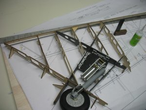
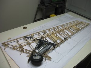
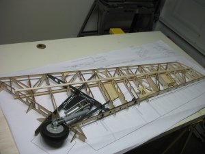


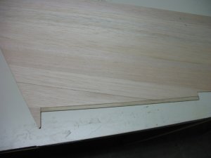
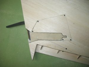
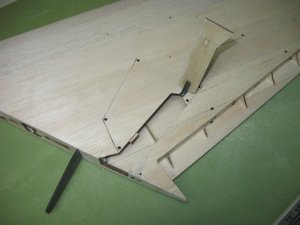
Photo 1: A strip of polyply needs to be glued onto the T.E. of the sheet over the aileron area. The sheet needs a 3/8 inch wide strip sanded so the polyply will be flush with the sheet when glued in place. The instruction manual and plans shows how to build a sanding tool to do this. Instead of using the sanding tool, I used a perma grit snading block. I measured back 3/8 of an inch from the T.E. and placed a metal straight edge on the line to give the sanding block something to sand against. Photo 1 shows the results after the polyply was glued in place.
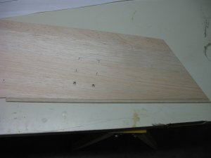
Photo 2: Plywood servo covers are glued on the inside of the sheeting over the aileron and flap servo covers. The covers are cut out before glueing the sheet to the wing.
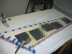
Photo 3: I took the advice of the guys recommending glueing the sheeting in place with hysol. This phot shows hysol on the ribs, spars, L.E., and T.E.
Photo 4: The sheet has been set in place. As per the instructions, tape is used to hold the front of the sheet in place. I used shot gun shell reload in zip lock bags to hold down the rest of the sheeting. The bags weigh 2 pounds each.
The bottom of both wings have been sheeted in this manner. Next is preparing the wing for top sheeting.
Kirk


With the bottom of both wings sheeted, it was time to prepare the wings and the sheeting and then sheet the top of the wings.
Photo 1: One of the tasks in preparing the wing was to make up the pylon mounting blocks. Once these were made they were glued to the inside of the bottom sheeting.
Photo 2: Polyply is glued to the top of the sheeting in the flap area. The sheeting was reccessed in the same manner as described in the above post for sheeting the bottom of the wing.
Photo 3: A piece of ply is glued to the inside of the top sheet to strengthen the area for the wing fence.
Photo 4 & 5: Plywood craddles are set at ribs 4, 10, and 15 and glued to the building board.
Photo 6: Sheeting is complete for the right wing. The left wing is sitting in the craddles and with weights while the glue sets.
Kirk


Vielflieger
User
Hi Kirk!
Supercool thread! I´ll keep readin´it!
The wing´s construction absolutely awesome. Bob did a great job engineering these wings. I love ribs and spars und balsa sheetings. And the whole thing with these "construction helper feet" is pretty smart...
Can u tell us something about the wings´weight? If possible... not in those strange "indian units" you Americans are used to


Best regards
Stefan
Supercool thread! I´ll keep readin´it!
The wing´s construction absolutely awesome. Bob did a great job engineering these wings. I love ribs and spars und balsa sheetings. And the whole thing with these "construction helper feet" is pretty smart...
Can u tell us something about the wings´weight? If possible... not in those strange "indian units" you Americans are used to


Best regards
Stefan
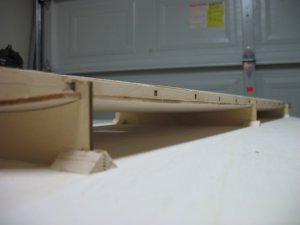
The leading edge was glued onto each wing with hysol. After the hysol set, they were razor planed and sanded down to the height of the bottom and top of the wing.
Photo 1: The center of the leading edge was found by measuring the height about every 10 inches down the length of the wing. A tick mark was placed at the half way point of each measurement. T pins were placed into the tick marks and a straight edge was placed on the T pins so a line could be drawn down the length of the leading edge.
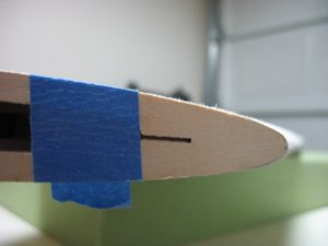
Phots 2 & 3: Plywood templates were taped in place at the root and tip of the wing.
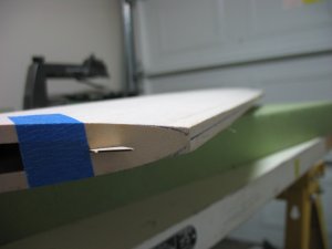
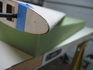
Photos 4 & 5: The leading edge was razor planed and sanded to the plywood templates.
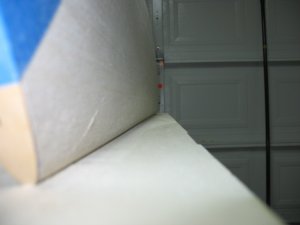
Photo 6: The leading edge was checked to make sure it was still straight after it was sanded by placing the wing on the bench and checking to see if there were any gaps between the leading edge and the bench.
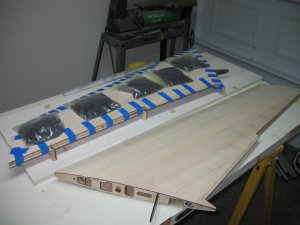
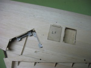
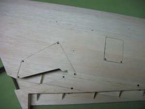
Photos 7 & 8: The servo and gear well covers were cut off of the bottom sheeting and plywood was glued to the inside of the covers. Plywood tabs were glued in place. The covers were put back in place and holes were drilled in the tabs to except screws. The covers were screwed in place and block sanded to the level of the wing sheeting.
Photos 9, 10 & 11: The main gear strut cover was made by laminating polyply to both sides of the plywood strut cover. The gear cover was removed and the strut cover hinge was glued in place. I will glue the hinges later when the same is done to the other wing.
The balsa servo and gear covers will have polyply laminated to them after the wing is glassed. The polyply covers overlap the gaps and will make the covers look like inspection covers.
Kirk


Hi Kirk!
Supercool thread! I´ll keep readin´it!
The wing´s construction absolutely awesome. Bob did a great job engineering these wings. I love ribs and spars und balsa sheetings. And the whole thing with these "construction helper feet" is pretty smart...
Can u tell us something about the wings´weight? If possible... not in those strange "indian units" you Americans are used to
Best regards
Stefan
Hi Stefan. Thanks for reading. I haven't weighed the wings yet. I still need to glue in the hinges and fit the ailerons and flaps. The hinges are designed so that the ailerons and flaps can be removed. After I get that completed, I'll weigh the wings and let you know what that number is in those funny little units you Europeans use

Kirk
RareBear811
User
Awesome! Great Pics and build! I will reading on too 
Best regards
Maggus

Best regards
Maggus
Awesome! Great Pics and build! I will reading on too
Best regards
Maggus
Hi Maggus. Thanks for the kind words and for reading.
Kirk
I'm waiting on flap hinging parts that were missing so I can't go any further on the wings. So, its on to the fuse.
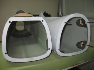
1st Photo: The flanges of the front and rear fuse sections were sanded smooth at the seams so they could mate evenly. Holes were opened in the flange of the front fuse section to accept the carbon fiber rods.
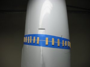
2nd Photo: Masking tape was placede around the perimeter of the front and rear fuse sections and aligment sticks were glued to the tape with ca.
3rd Photo: The aluminum recepticles were screwed to the plywood tongues and balsa spacers were glued to the back of the plywood tongues. The balsa spacers were sanded to fit against the fuse. Once the fit was found for each recepticle, they were hysoled in place.
Photo 4: After the hysol set, the masking tape and alignment stickes were removed. A perfect fit is the result.
Kirk


Next up is adding the wing mounting formers into the fuse.
Photo 1: The openings in the wing root area of the fuse were opened.
Photos 2, 3, & 4: Formers F3, F4, and F4A were sanded on both sides with 80 grit. Formers F3 and F4 are end grain balsa sandwiched between carbon fiber. Former F4A is a carbon fiber plate. F4A is glued to the front side of F4. Plywood former F4B is glued to the back side of F4. The wing spar bolt inserts was glued to former F4A with hysol.
Photos 5, 6, & 7: The F3 former and F4 former assembly was placed in the fuse and the wings are put in place. The wings were raised above the the bench so that the fuse does not touch the bench and they are bolted to the F4 former assembly. Tape is used to make sure the leading edge mates correctly to the fuse. F3 is placed against the phonelic tubes an formers and phonelic tubes are hysoled in place.
Photo 8: Lastly, the canopy deck and engine cover hatches are set in palce and tape is used to pull the fuse sides so that they were even with the hatches.
Tomorrow after the hysol has set, the wings will be removed
Kirk
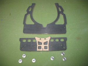
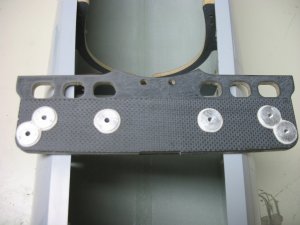
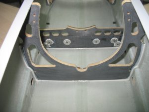
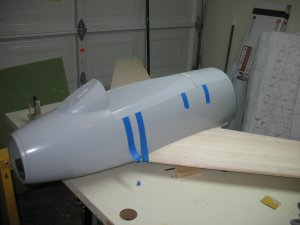


I received an email today from Schubeler today letting me know the fan will be shipping tomorrow.
Here are the spec's for the fan:
DS-94-DIA HST with DSM6745-700
Inner diameter: 128 mm
Fan Swept Area: 94 cm^2
Weight including motor: 1330g (2.9 lbs)
Thrust Range: 22.5 to 29.2 lbs (100-130 N)
Exit Velocity (Efflux): 94-108 m / s
RPM: 28,000 - 30,500
Amps: not given but calculated based on cell count and watts: 144A to 182A
Input Watts: 6.6 to 9.7 kW
Number of Cells: 12S to 14S
The DS-94 and the XPS Dynamax Pro II are the same size fan so for comparison these are the spec's posted on the XPS website:
XPS Dynamax Pro II
Inner diameter: 128 mm
Fan Swept Area: not given
Weight including motor: not given but from other threads it was stated at over 3 pounds
Thrust Range: 29 lbs
Exit Velocity (Efflux): not given
RPM: 36,250
Amps: 205A
Input Watts: not given but calculated based on cell count and amps: 12.5 kW
Number of Cells: 16S
So, the comparison shows the following when each fan produces 29 lbs of thrust:
- The DS-94 runs at a lower amp draw than the Dynamax
- The DS-94 runs on 14 cells vs the Dynamax running on 16 cells
- The DS-94 runs at 5750 rpms less than the Dynamax
- The DS-94 consumes 2.8 kW less than the Dynamax
- The DS-94 weighs less than the Dynamax
The comparison shows the DS-94 is a lighter setup (fan weighs less and less number of cells required) with longer flight times (less amp draw and less kw consumed) when carrying the same amount of mAh.
Kirk
Erik van Schaik
User
Hi Kirk!
Your building qty is very nice! I only see glue where one wants it without fingerprints LOL!
I didn't realize big jets have less balsa and more ply. It's a great construction.
I never understood the xps heatgun and the data shows it isn't worth living IMO.
You'll like the HST fans. I have seen Jurgens F20 fly several times and tough it isn't s speedplane it is a great fan for thrust and superb scale performance. The Sabre will be very happy with your choice.
I am looking forward to your cell choice and the motorruntime DS vs XPS.
keeps those pics coming!
Hi Erik,
Thanks. I've been building for many years and perfer to build an airplane rather than assemble an arf.
I do really like the Schubeler HST fans. I have the first version of the DS-77 HST in a Ziroli Panther I built. The Panther weighs 28 pounds (12.7 kg) and the DS-77 HST flies it reall well. I took the Panther to E-Jets International in September and received the "Best Finish Award".
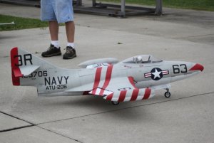
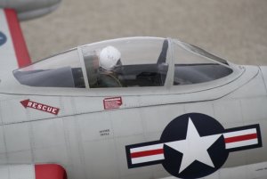
The Panther's build photos can be seen on RCUniverse: http://www.rcuniverse.com/forum/m_9652030/mpage_1/key_/tm.htm. Below are some photos from E-Jets International.
This is a video of the 5th flight of the Panther:
http://youtu.be/TK5Hd3RnNJk?hd=1
Here is a video from E-Jets International. I had cooling problems with the controller (it was much warmer than wherer I live) and the Panther was belly landed after the controller thermal shut down. Daniel Schubeler helped me fix the cooling issue.
http://youtu.be/pWczKaK3f78?hd=1
I have been using Thunder Power 65C 7700mAh batteries. After the flights of the Panther in the videos above I put back 2980 mAh. The HST fans seem to be very effiecient because you don't need to use full throttle unless you go verticle.
Kirk


Anhänge
Thanks Hoeby. I have been using Schulze controllers. I used the 160A controller in the Panther and will be using the 300A controller in the F-86. The 300A controller is the last Schulze I have so I will use it but I think I will start using the MGM Compro controllers for any future projects.
Kirk
Kirk
With the wings mounted, it was time to move to the rear fuselage section.
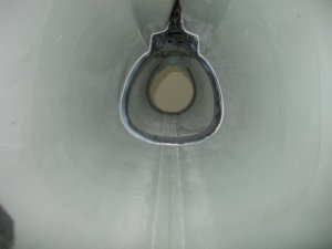
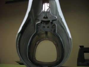
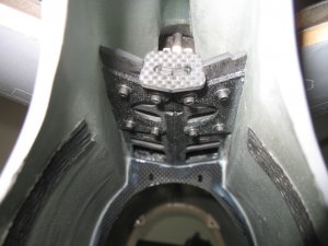
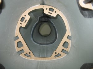
Photo 1: The carbon fiber formers were prepared by sanding them with 80 grit. The aluminum vertical stab recepticles were screwed in place and the horizontal stab mounting plates were glued together using a plywood jig to set the proper dihedral angle for the horizontal stabs.
Photo 2: The vertical stab has 2 carbon fiber rods sticking out of the bottom that go into the aluminum recpticles so the vertical stab can be attached to the fuse. Holes for the carbon fiber rods and the 2 set screw holes were opened up at their scribed lines. The slots for the horizontal stab mounting tongues were also opened at their scrib lines. The location of the full-sized former is found by placing it into the fuse and putting the forward carbon fiber rod of the vertical stab into the aluminum recepticle. The former is then adjusted until the set screw is even with the hole in the side of the fuse. Once the location is found, I used the stick alignment technique to ensure the vertical stab lined up properly with the fuse.
Photo 3: Next, the set crew was tightened and the former was hysoled in place.
Photo 4: The location of the small, partial former for the rear carbon rod of the vertical stab was found in the same manner as the full sized former and it was hysoled in place.
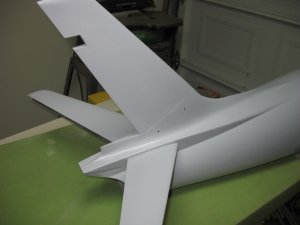
Photo 5: After the hysol around the vertical stab mounting formers set, the horizontal stab mounting plate was set in place and the stabs were attached to check the fit. Everything fit so the stabs and mounting plate were removed. A bead of hysol was run just above the slots and on the vertical stab formers where the mounting plate touched. Grease was smeared on the mounting plate tongues to prevent hysol from adhereing to them. The mounting plate was installed and the hortizontal stabs were attached and the front of the plate was hysoled to the side of the fuse.
Photo 6: The plywood elevator servo mounting former was hysoled in place.
Photo 7: The final results.
Kirk


Erik van Schaik
User
Great Panther!
The HST really matches the scale performance. I bit odd landing (coming from high and suck to the strip, I'd expected a better gliding ratio )
)
Now i understand why these kits are so expensive. Lotsa laser and milling parts.
greets!
Erik
The HST really matches the scale performance. I bit odd landing (coming from high and suck to the strip, I'd expected a better gliding ratio
 )
)Now i understand why these kits are so expensive. Lotsa laser and milling parts.
greets!
Erik
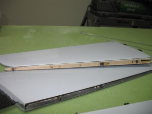
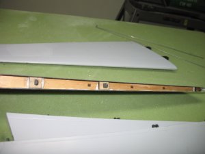
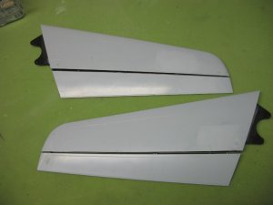
The horizontal stabs and elevators have been hinged. This process is done by first glueing the hinge halves into the elevator.. The hinge pin is run through all of the elevator hinge halves and a spacer is used to set the proper depth of the hinge half. After the glue sets, the hinge pin is removed and the the horizontal stab hinge halves are added, then the hinge pin is placed back on the elevator hinge halves. The horizontal stab hinge halves are glued into the horizontal stab and the depth of the hinge halves are set by using a spacer at the tip and root of the stab between the stab and the elevator. The photos below where taken after the hinge halves had been glued into the horizontal stabs and elevators.
Photo 1: Shows the hinges glued into the elevators.
Photo 2: Shows the hinges glued into the horizontal stabs. I will clean up the excess glue later.
Photo 4: Shows the elevators attached to the horizontal stabs with the hinge pin.
Up next will be adding the hinge pin tube and leading edge to the elevators. This will most likely occur after the holidays.
Kirk


Ähnliche Themen
- Antworten
- 5
- Aufrufe
- 2K
- Antworten
- 3
- Aufrufe
- 2K

