Hello, and sorry to write in English!
At the weekend I changed the angle incidence of the main wings, not the EWD. The flamingo should have around 4º of angle in the main wings (around 18 mm from the floor to the wing tip). Mine had in one wing 22 cm, and on the other 13 cm.
Using the soldering iron I applied heat to the steel pins in the main wing spar, and with some strength and pliers moved them out of their position. It took me approx. 5 heat and pull tries with pliers to each of the steel pins (so 4 pins, and approx 20 heat tries). After, reworked the 4 holes, 2 in each wing, with the 3 mm drill (perhaps it should have been the 4 mm drill to have more tolerance). Glue them again with UHU Endfest 300, measure the height from the floor to each wing tip, and use under the left wing a mug in order to achieve the height desired. To my surprise, on the left wing it did not go further up than 16 cm. On the right wing it went down to 19 cm. Fairly good is better than perfect, so I just left it like this to dry.
The final result is: right wing 18,5 cm, left wing 14,5 cm. (again, I think I should have used the 4 mm drill, instead the 3 mm for more tolerance).
This is the second time I use this method to the wings.
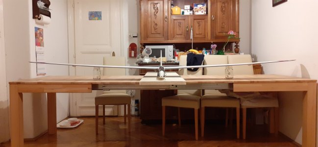
To measure an straight, 3 meter wingspan glider in a flat on the floor (for having a flat reference surface) is not an easy task (fuselage is difficult to maintain in a 90º straight position).
The flamingo has been flying very well for the last 10 years with a weight of 3 kg, to 3,2 kg. Now, I hope even a bit better, specially for the left wing aileron turns, which were more kind of a diving experience, opposed to a gentle turn in the right wing (the right turns were much better and easier).
I enclose a link of alpina 4001 which explains the system of gluing taking consideration of the wings incidence in posts 34-35-36.
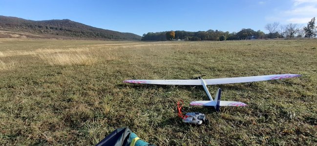
The picture is of last time flying with the flamingo without correcting the incidence.

 www.rc-network.de
Cheers!
Nacho Martínez
At the weekend I changed the angle incidence of the main wings, not the EWD. The flamingo should have around 4º of angle in the main wings (around 18 mm from the floor to the wing tip). Mine had in one wing 22 cm, and on the other 13 cm.
Using the soldering iron I applied heat to the steel pins in the main wing spar, and with some strength and pliers moved them out of their position. It took me approx. 5 heat and pull tries with pliers to each of the steel pins (so 4 pins, and approx 20 heat tries). After, reworked the 4 holes, 2 in each wing, with the 3 mm drill (perhaps it should have been the 4 mm drill to have more tolerance). Glue them again with UHU Endfest 300, measure the height from the floor to each wing tip, and use under the left wing a mug in order to achieve the height desired. To my surprise, on the left wing it did not go further up than 16 cm. On the right wing it went down to 19 cm. Fairly good is better than perfect, so I just left it like this to dry.
The final result is: right wing 18,5 cm, left wing 14,5 cm. (again, I think I should have used the 4 mm drill, instead the 3 mm for more tolerance).
This is the second time I use this method to the wings.
To measure an straight, 3 meter wingspan glider in a flat on the floor (for having a flat reference surface) is not an easy task (fuselage is difficult to maintain in a 90º straight position).
The flamingo has been flying very well for the last 10 years with a weight of 3 kg, to 3,2 kg. Now, I hope even a bit better, specially for the left wing aileron turns, which were more kind of a diving experience, opposed to a gentle turn in the right wing (the right turns were much better and easier).
I enclose a link of alpina 4001 which explains the system of gluing taking consideration of the wings incidence in posts 34-35-36.
The picture is of last time flying with the flamingo without correcting the incidence.
Alpina 4001 Elektro (Tangent): Baubericht!
Fortsetzung... Fortsetzung... Weiter geht es nun mit dem Leitwerk. Das Seitenruder besitzt drei Einschnitte auf der Anlenkungsachse. Hier werden 3 Augenschrauben mit der Lochseite hinein gesteckt. Im Leitwerksruder selbst verläuft ein Röhrchen, wo ein CfK-Stab hindurch gesteckt wird. Dieser...
Cheers!
Nacho Martínez
 . I don't know why but i accepted this behavier. It's just the Flamingo
