U-Boot: USS Nautilus - Eigenbauprojekt

So, ich war nicht faul. Aber da ein Boot nach der Lackierung mit 2K-Klarlack genausso aussieht wie vorher, hab ich da keine Fotos gemacht. Jetzt geht's an die Innereien und wegen der genauen Planung und den guten Werkzeugen geht das jetzt recht flott. Antriebe, Servos und Druckschalter sind Installiert:

DSC02011_zps7ldhf6fq.jpg


DSC02012_zpswyucbeex.jpg


DSC02013_zpsgroyji9d.jpg


Der Druckschalter sitzt in einer Plexiglas-Klammer und passt saugend an seinen Platz:

DSC02014_zpsi4fu1etf.jpg


Der Antriebsstrang ist installiert. Alles großzügig ausgelegt. Die Raböschkupplung kann in der Länge arbeiten und so kommen auch keine ungewollten Kräfte bei unterschiedlicher Wärmeausdehnung auf den Antrieb:


DSC02015_zpssrhrdfk6.jpg


Die Anlenkungen sind mit Faltenbalgen gedichtet. Die zusätzliche Stopfbuchse ist für den Fall, dass die Antenne nach draußen muss:

DSC02018_zpsvhsups37.jpg


Platz ist in der kleinsten Hütte, aber hier ist es wirklich eng geworden. Nur zu erreichen mit selbstgebautem Werkzeug, u.a. einem verlängerter Inbusschlüssel.

DSC02017_zpszca7c9lp.jpg


Und sobald der Deckel drauf ist, sieht man die ganze Fingerakrobatik nicht mehr:

DSC02020_zpstqonhedq.jpg
 
So, eine Woche Löt- udn Verkabelungsorgie hinter mir. Jetzt ist alles installiert. Mal eine kleine Übersicht:

DSC02032_zpsvlbodani.jpg


Vorne der 4S 4100er LiFePO Hauptakku und ein 1600er LiFePo Empfängerakku:

DSC02033_zpsdhje49x8.jpg


Hinten die Servos, der Lageregler, Druckschalter, Motoren und die Tauchtanksteuerung mit Hall-Sensor:

DSC02034_zpsgbwz6nqu.jpg


Alle Kabel gut gesichert, damit sie nicht von den Außenläufern geschreddert werden:

DSC02035_zpskqtooroo.jpg


DSC02036_zps7lrknwdf.jpg


DSC02037_zpsuqea9zsg.jpg


Die Brushless-Regler hatten noch Platz neben, bzw in der Tauchtanksteuerung:

DSC02039_zpsixvoahs6.jpg


Vorne der Corona-Empfänger und der ganze Kabelbaum. Alles mit Ferritkernen entstört:

DSC02038_zpsluspbkcu.jpg


Programmiert und Kalibriert ist inzwischen das ganze auch. Also kann langsam das Waser kommen.....
 
Zum trimmen ahtte ich die vodere Hälfte des Decks noch unten, damit ich zugang zum Bug hatte, wo Hartschaum und Blei untergebracht wurde. Jetzt konnte das Deck endgültig drauf. Sieht wie ein fast fertiges Boot aus:

DSC02098_zpsctcj5wwt.jpg


DSC02096_zps68qgoxhp.jpg


DSC02095_zpszee6cymg.jpg
 
O.K., um das hier am Laufen zu halten. Der erste imrprovisierte Bausatz ging an einen Freund in den USA, der mir bei der eralisierung der Nautilus sehr geholfen hat. Ohne Ihn wäre das Boot nicht so schön geworden. Er schreibt einen Work In Progress Report und ich werde den hier nach und nach auch posten. Leider nur in Englisch. Ach ja, Ladies und Gentlement.....die Arbeit von David Merriman:

I first became aware of the model work of Andreas Schmehl a few years back while
checking out the articles at one of the few forums dedicated to r/c submarine model
building. His work-in-progress (WIP) -- a format of article writing that is heavy on inprogress
photos with supporting text -- dealt with the construction of a 1/23 scale, U-1.
Germany's first combat submarine. It was the most comprehensive and well laid out
WIP I had ever read.

That multi-part article had everything: CAD design, CNC'd hull masters; 3D printed
detail parts; hard-shell, GRP hull tools; RTV rubber tools for the small stuff; GRP lay-up;
resin casting; WTC design and manufacture; trimming; detailing; and painting.
As Andreas put it: "I mainly use CAD to create a virtual model of the hull and the interior
technical structure. From that I produce the 3D files for manufacturing 3D-printed parts
and for milling preforms for the GRP tooling". What Andreas calls 'preforms' we
American's understand these as masters, or patterns.
Once Andreas had worked out the 'plans' in CAD, he sent the files to a second party
fabricator who used them to cut machinable plastic medium via CNC milling machine,
and to poop out plastic parts via 3D printer. Those parts, back in Andreas' hands,
becoming the masters of off which he would produce the actual model parts.
Masters by robot. Tooling and model parts by the good doctor.
SkyNet, call your office!


His U-1 article showed me, in a very well laid out article, the use of computers and
mechanized subtractive and additive item manufacture as part of the model building
process.


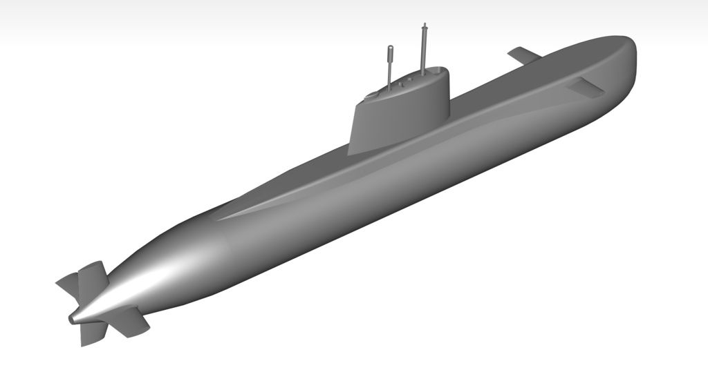
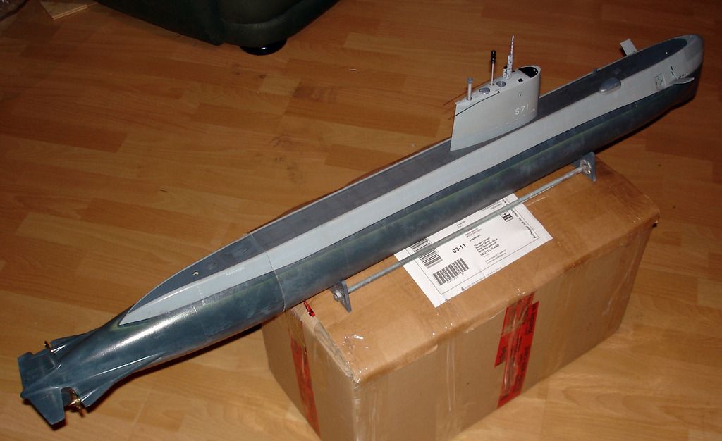
Andreas has done the same thing with his current r/c submarine project: a dry-hull 1/87
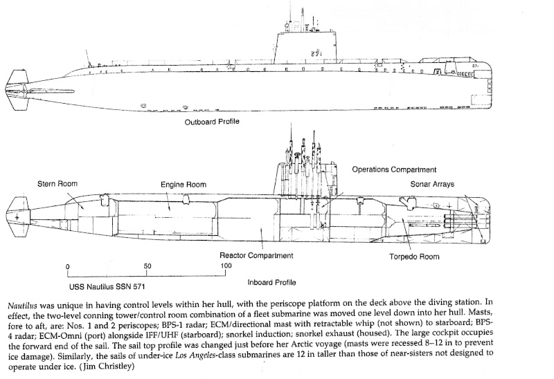
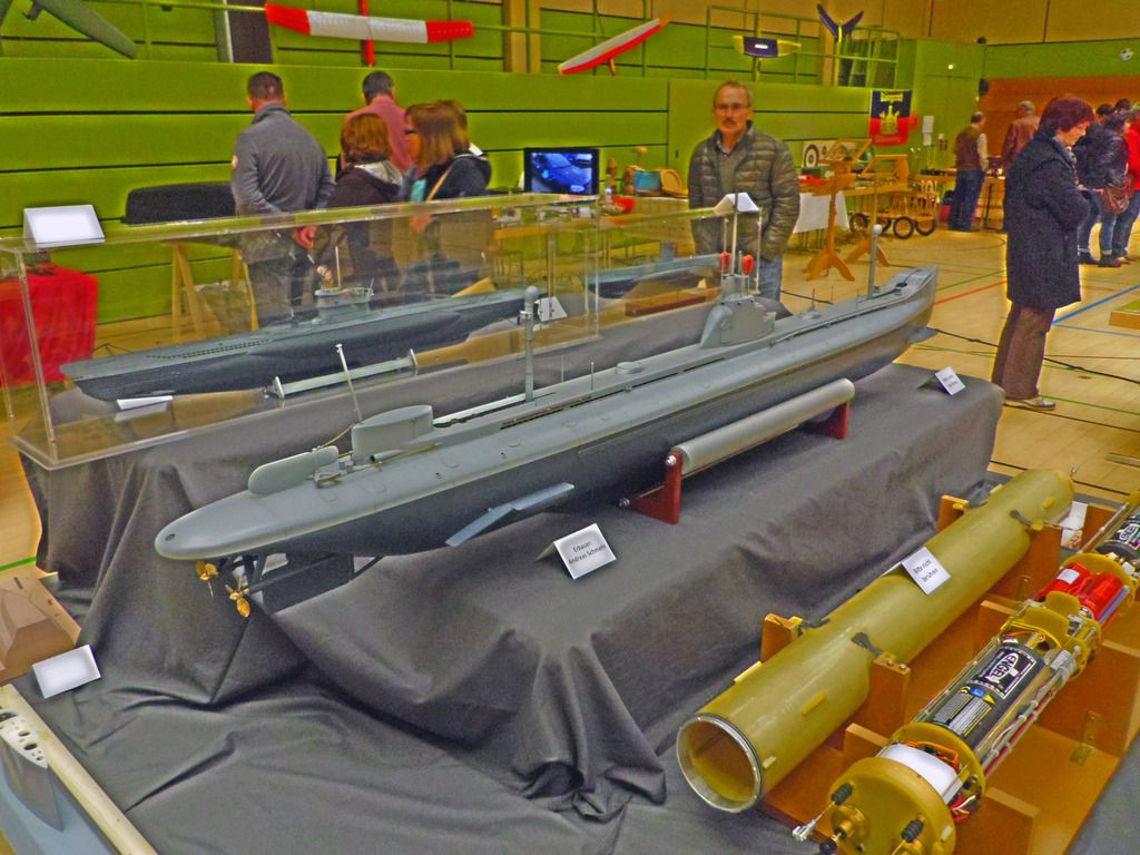
scale model kit of the famous, USS NAUTILUS.
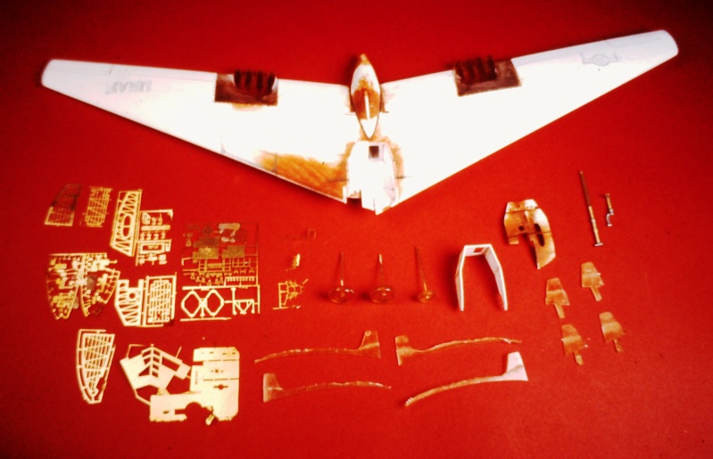
His first USS NAUTILUS, assembled from his kit -- as is the European practice -- was
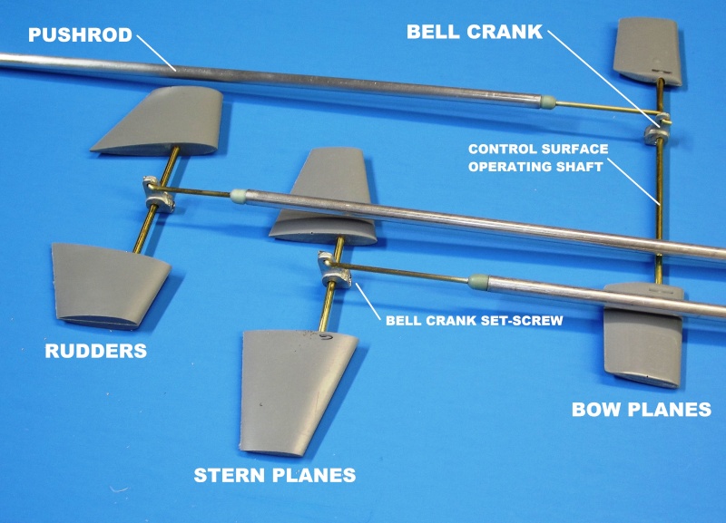
configured as a dry-hull type r/c model submarine. With the exception of the sail and a
portion of the stern (where the stern plane, rudders and propeller shafts make up to
their respective running gear and linkages) the entire hull is dry.


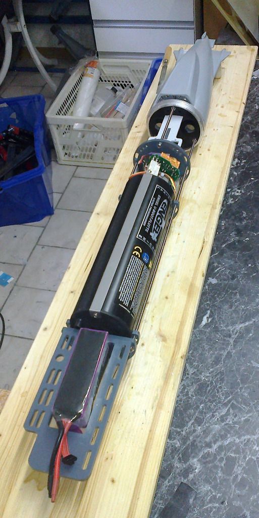
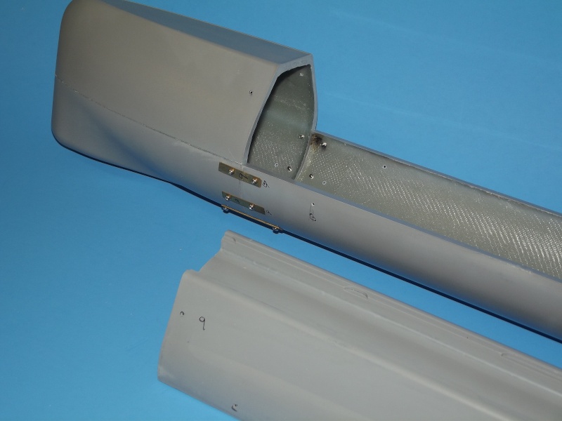
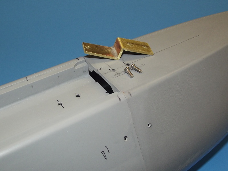
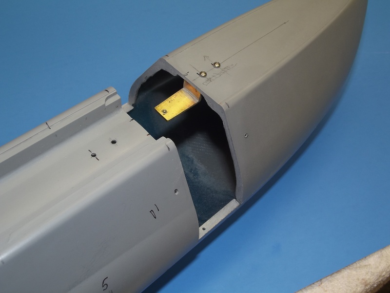
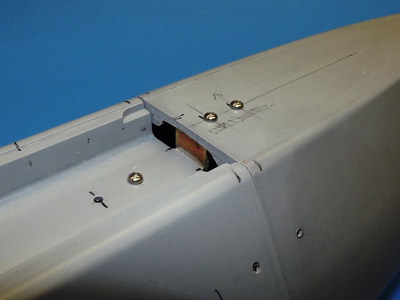
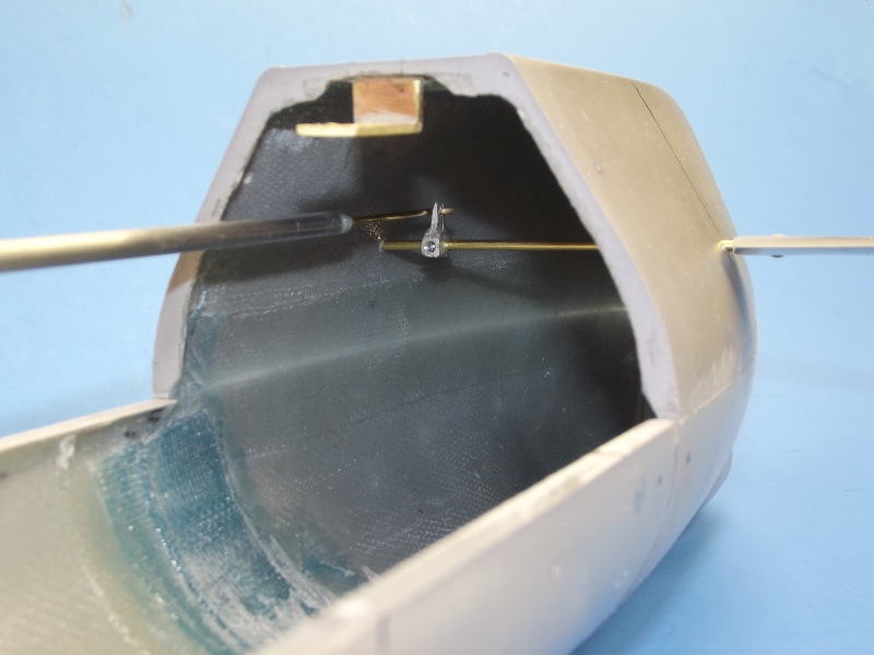
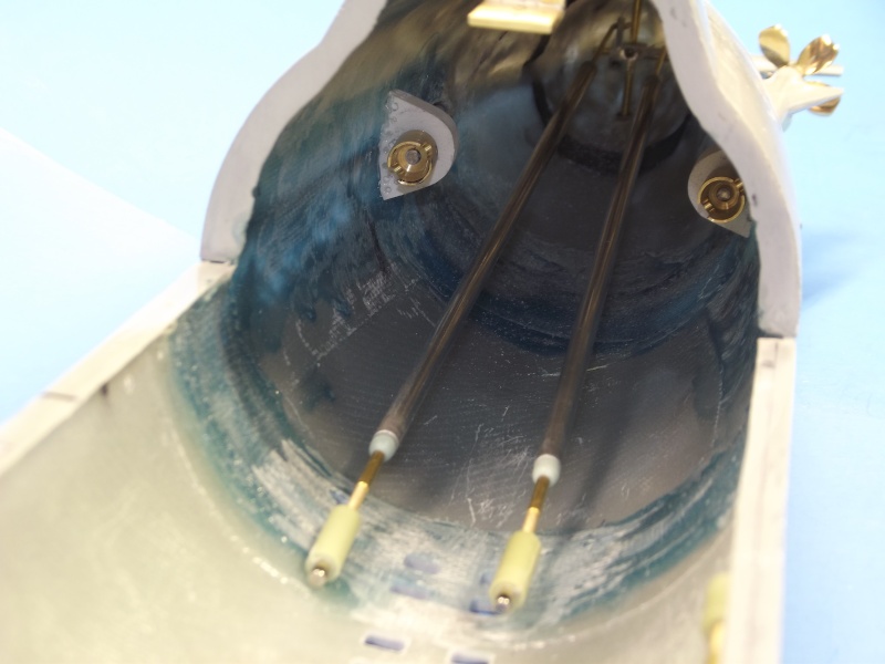
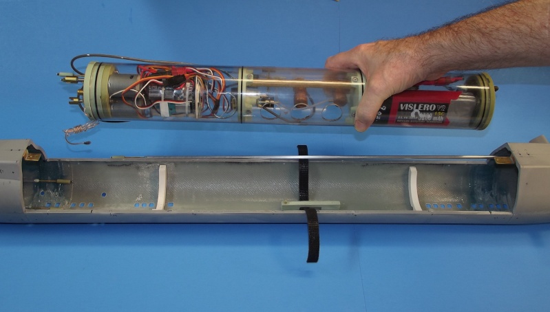
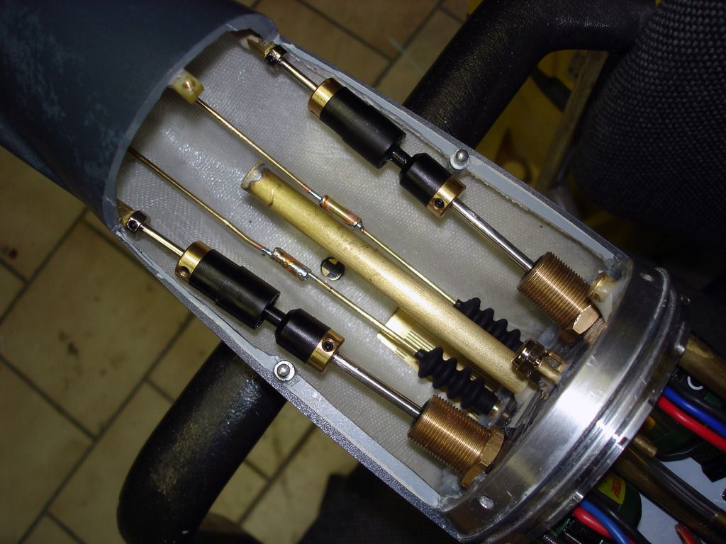
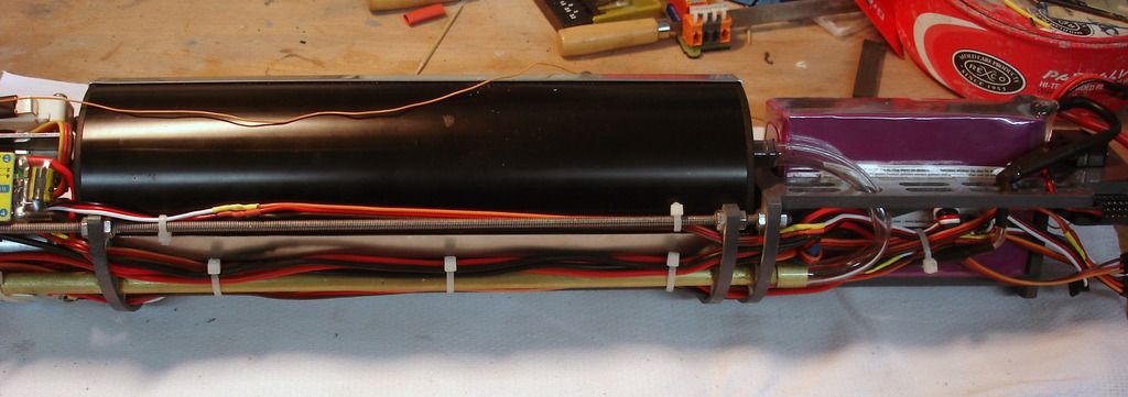
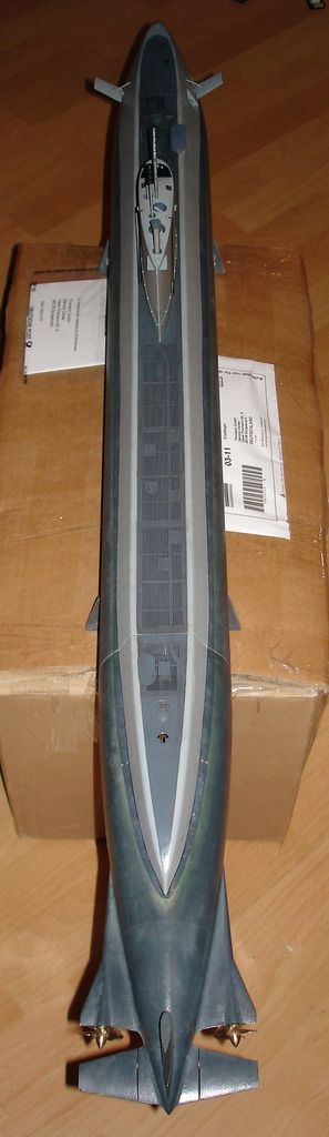
Another European practice -- most suitable for dry-hull types r/c submarines -- is to
access the interior through a set of bayonet rings that seal with an o-ring. Set into the
forward and after sections of the model, the bayonet rings produce a radial break
between the two. To access the interior all that is required is a slight rotation of the hull
halves to free the lugs of the bayonet rings and simply pull the two hull halves apart. A
positive, quick, easy and pressure-proof closure method. Attaching the equipmentdevice
mounting structure to the stern exposes everything when the forward section of
hull is removed.

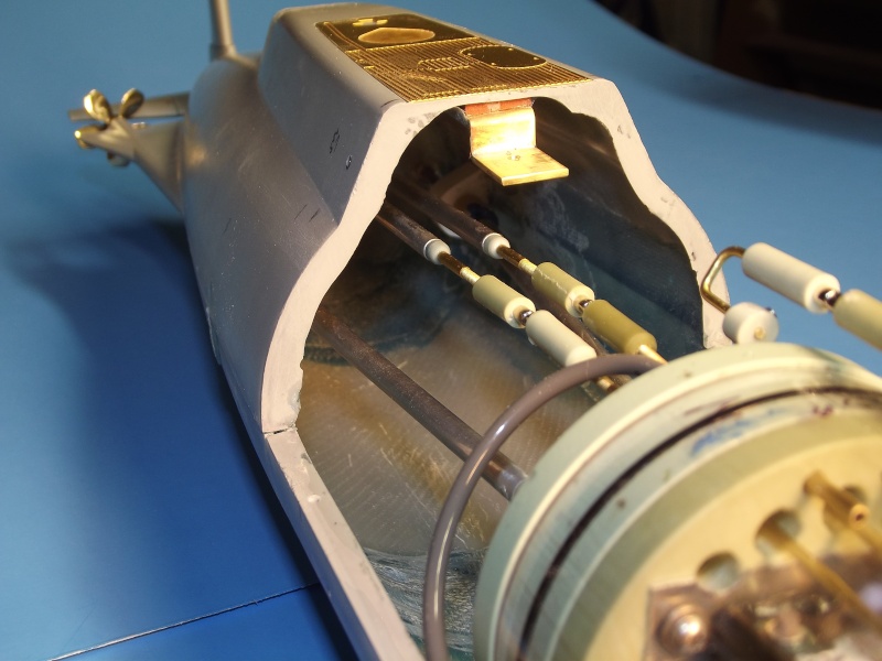
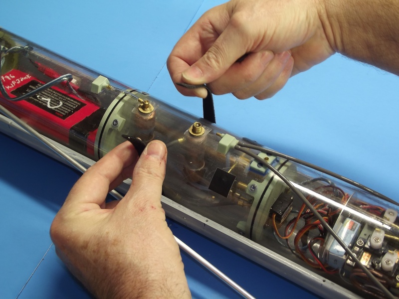
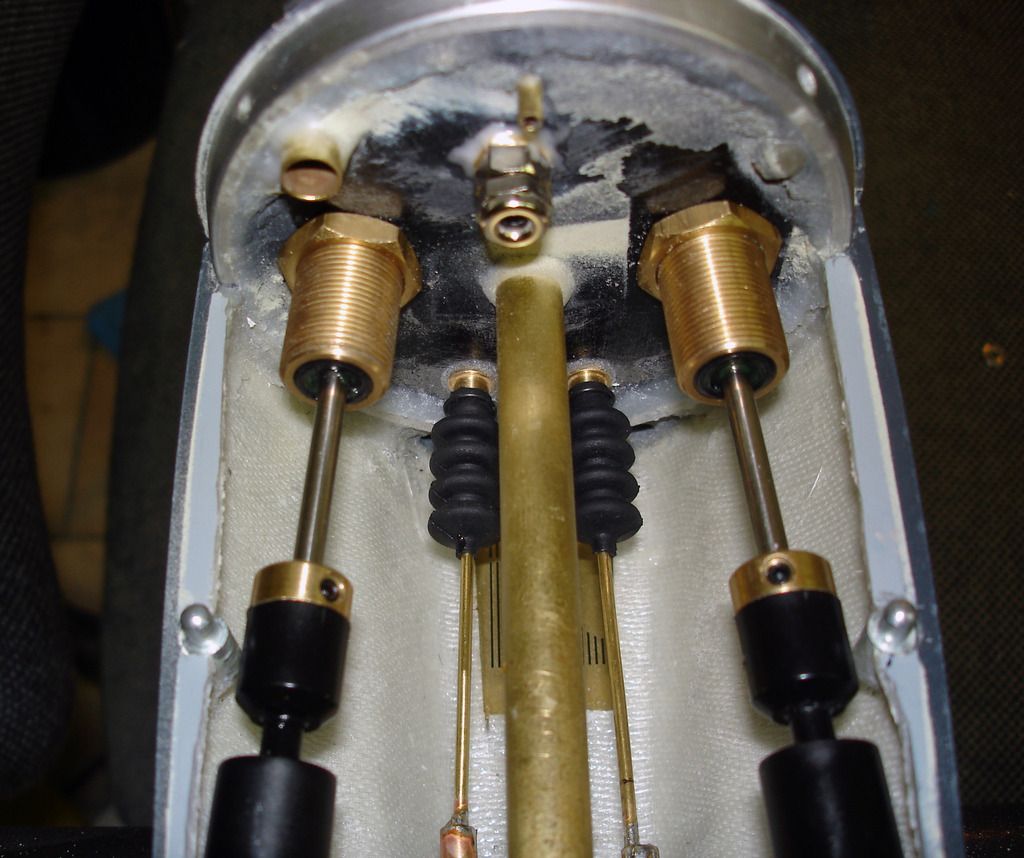
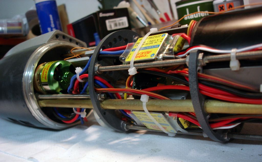
Unlike wet-hull type models -- which require opening the hull through a horizontal
equatorial break, removing the WTC, and only then gaining access to the devices by
removing the end-caps of that WTC -- the dry-hull bayonet rings make for excellent
access to the internals for repair, de-watering, adjustment and maintenance tasks.

13062015129_zpsem2xjrwb.jpg


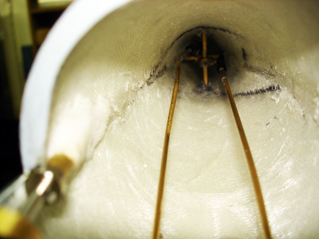
The advantage of the dry-hull is that there is plenty of available volume in which to stick
all the propulsion, control, and ballast sub-systems.
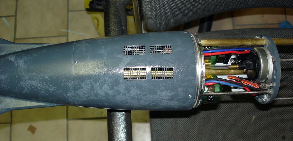
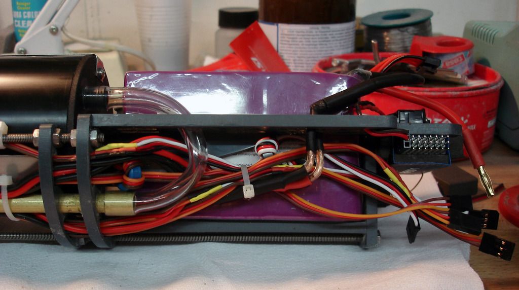
However, as the superstructure and portions of hull above the waterline will displace so
much water when they are immersed, it takes a great deal of water weight --- taken into
an internal ballast tank -- to create the force needed to counter the buoyant force
produced by all that displacing structure. A big ballast tank takes up valuable real-estate
within the tight confines of the hull.
The need for such a large internal ballast tank denotes the major disadvantage of the
dry-hull type submarine.

DSC01844_zps63ace771.jpg


DSC01845_zpsc93f919b.jpg


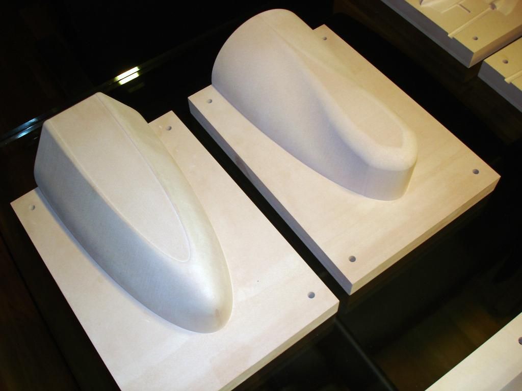
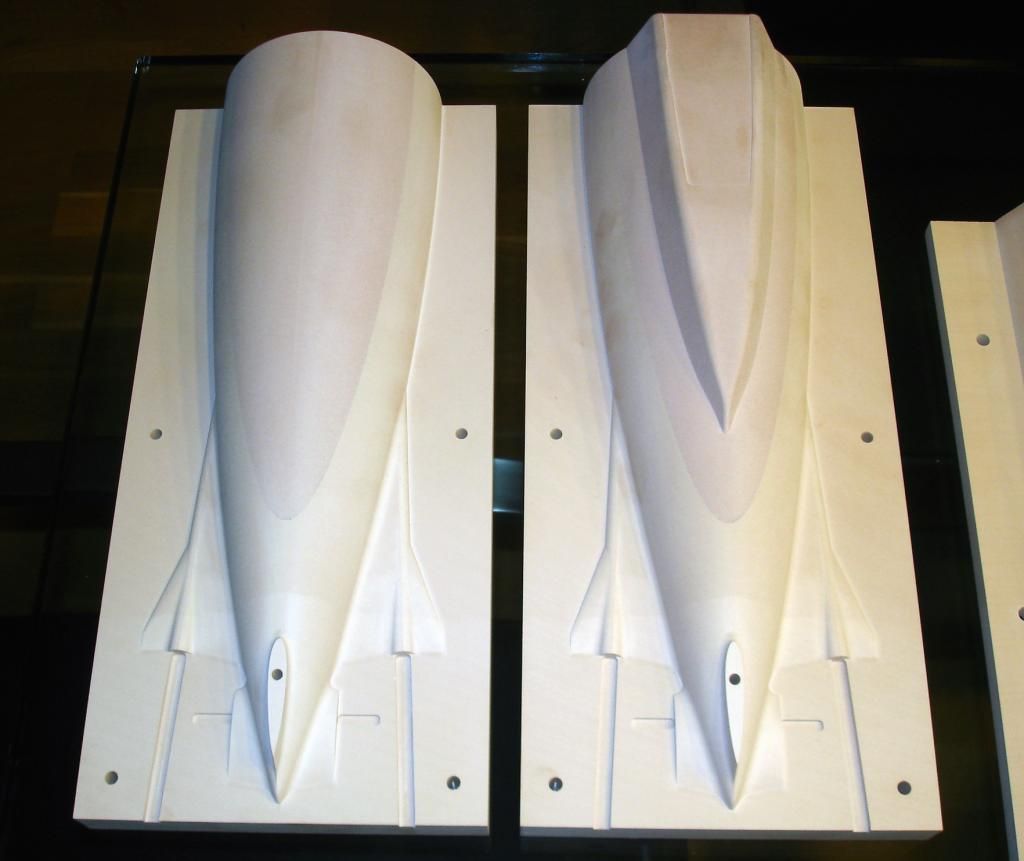
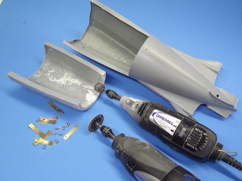
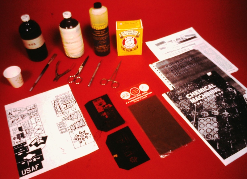
Andreas followed the same manufacturing methodology with his NAUTILUS kit. A
second-party produced the masters from which he would make to tooling needed to
create the model parts. Here we see some of the CNC milling-machine cut masters.


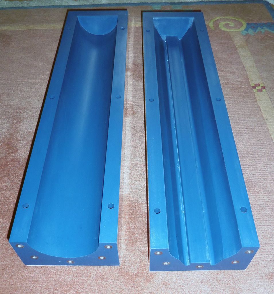
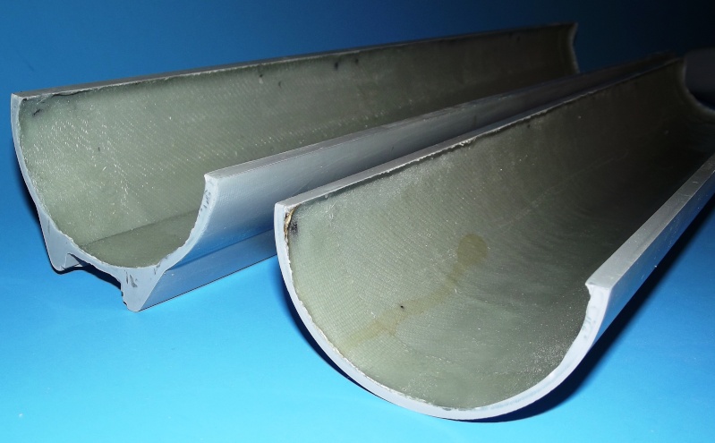
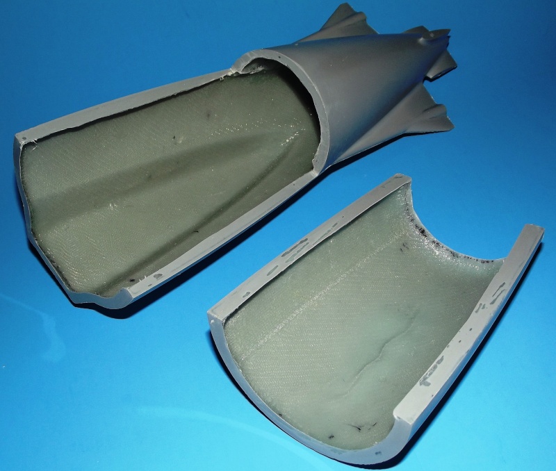
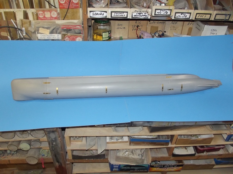
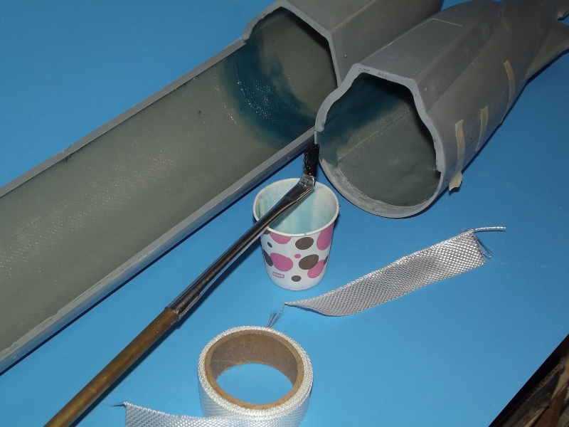
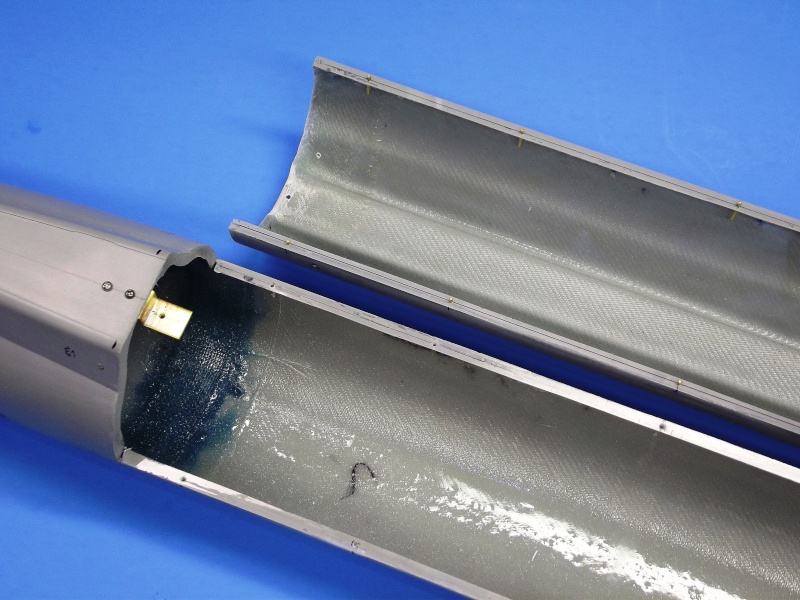
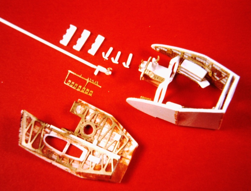
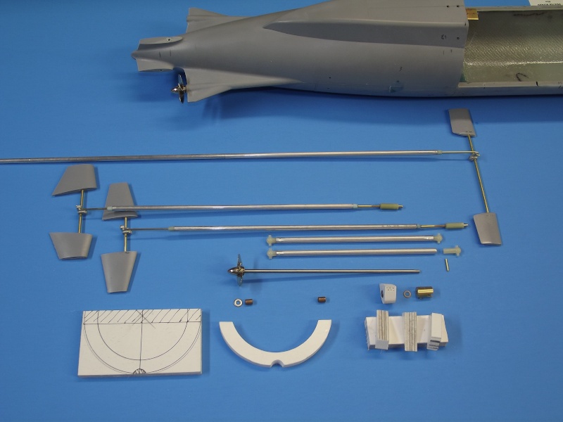
Off those CNC cut masters Andreas laid-up these GRP hard-shell tools. A total of eight
tools required to render all the hull and sail parts. Those GRP parts rendered as very
thin section structures.


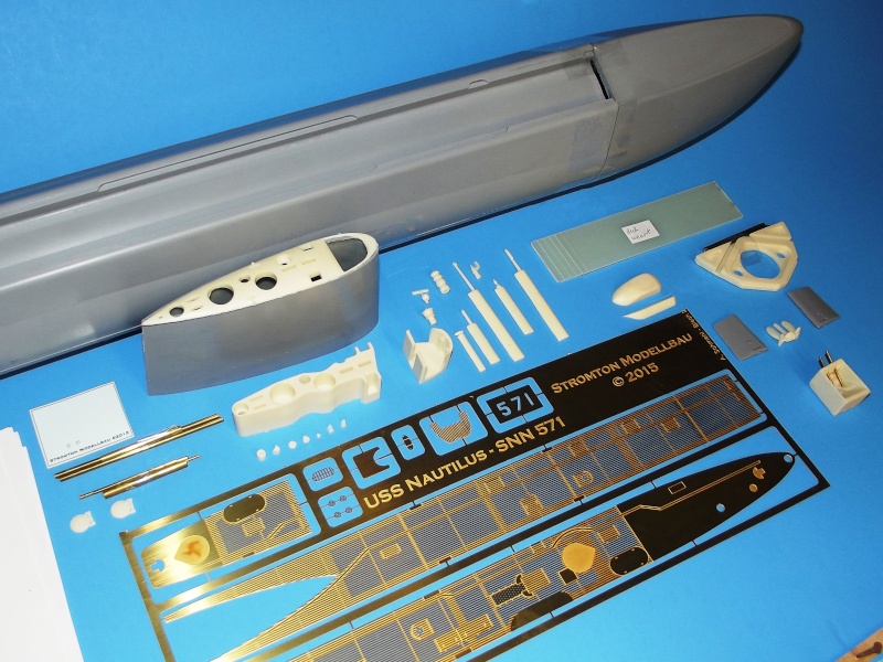
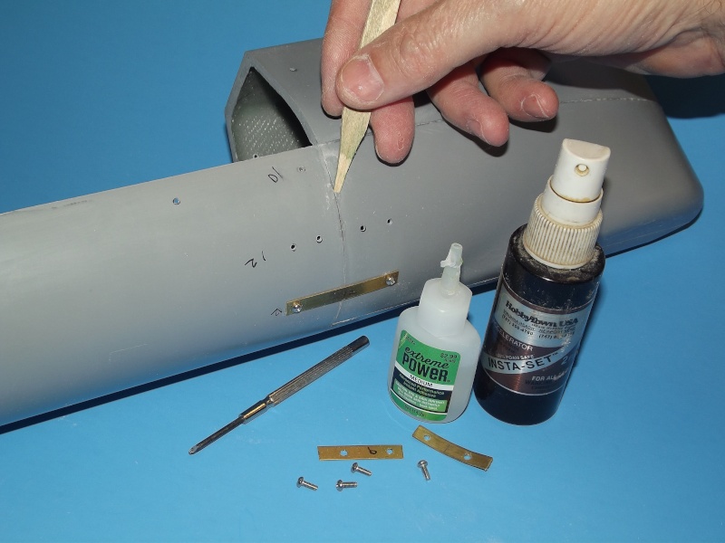
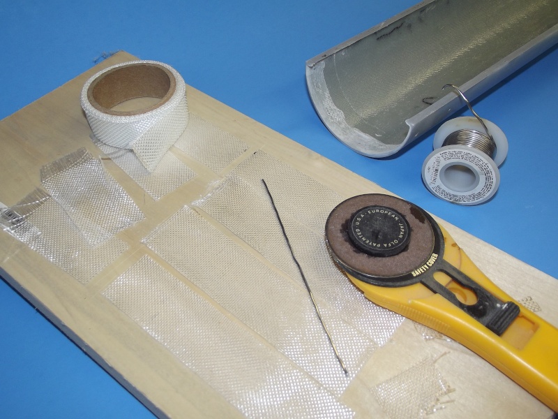
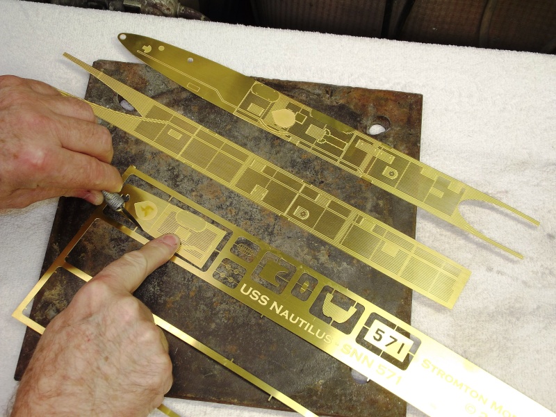
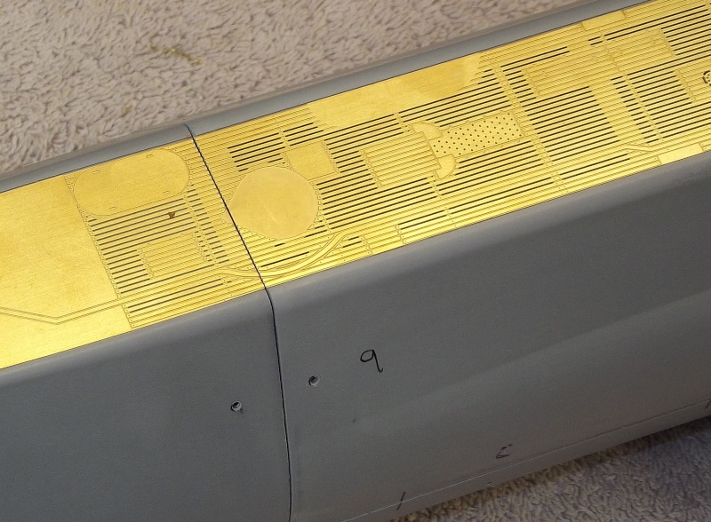
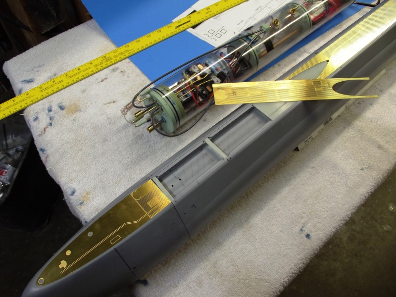
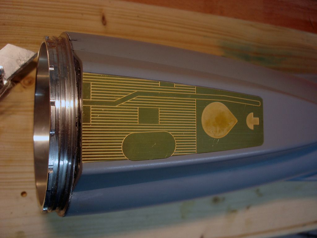
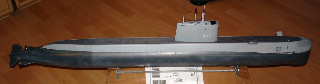
In addition to the resin and GRP parts he produced from this tooling, Andreas also
produced the art work from which he had acid-etched a fret of wonderfully detailed
deck, radar antenna reflector, other detail parts ... and even a painting mask needed to
produce the white '571' on the sides of the sail.
Also provided in the kit is a set of water-slide type decals containing the white draft
markings for the hull and upper rudder.


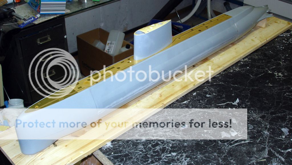
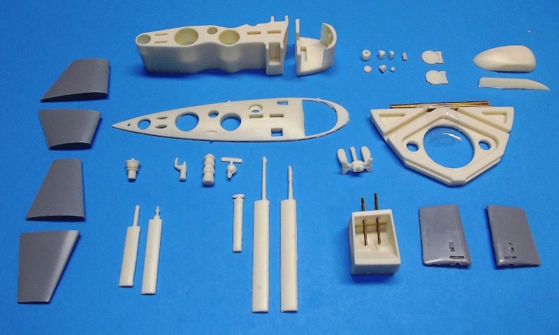
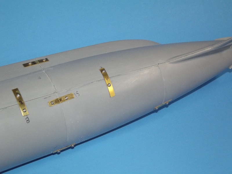
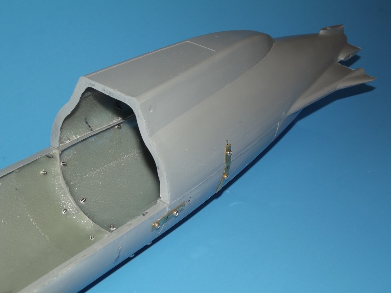
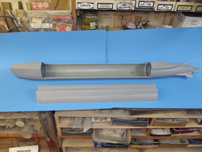
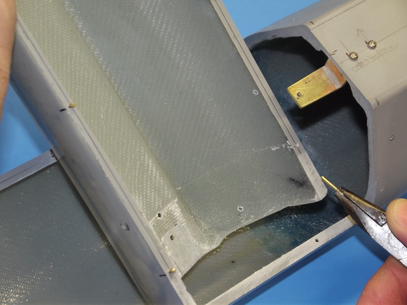
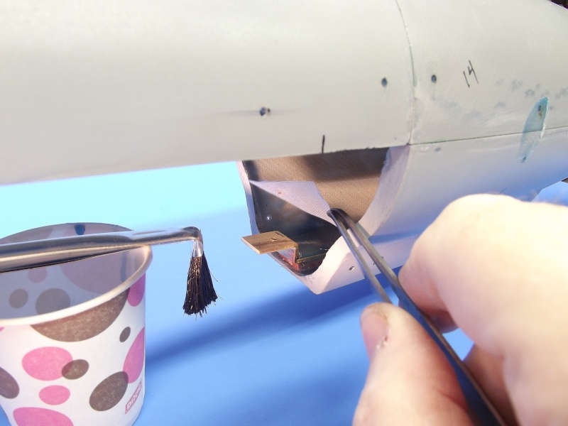
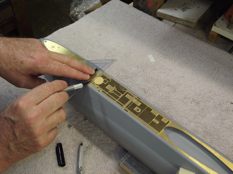
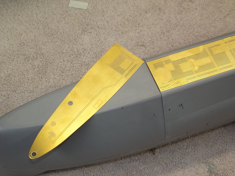
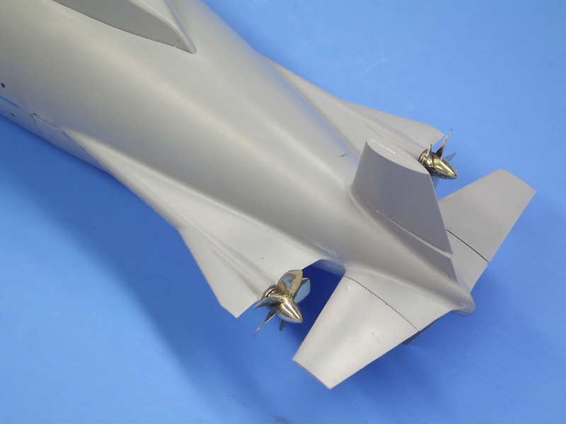
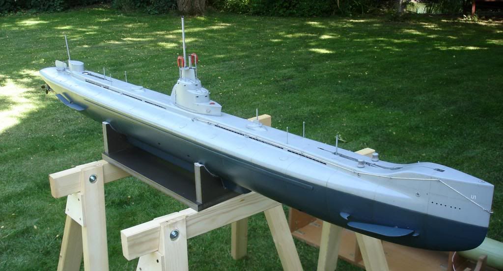
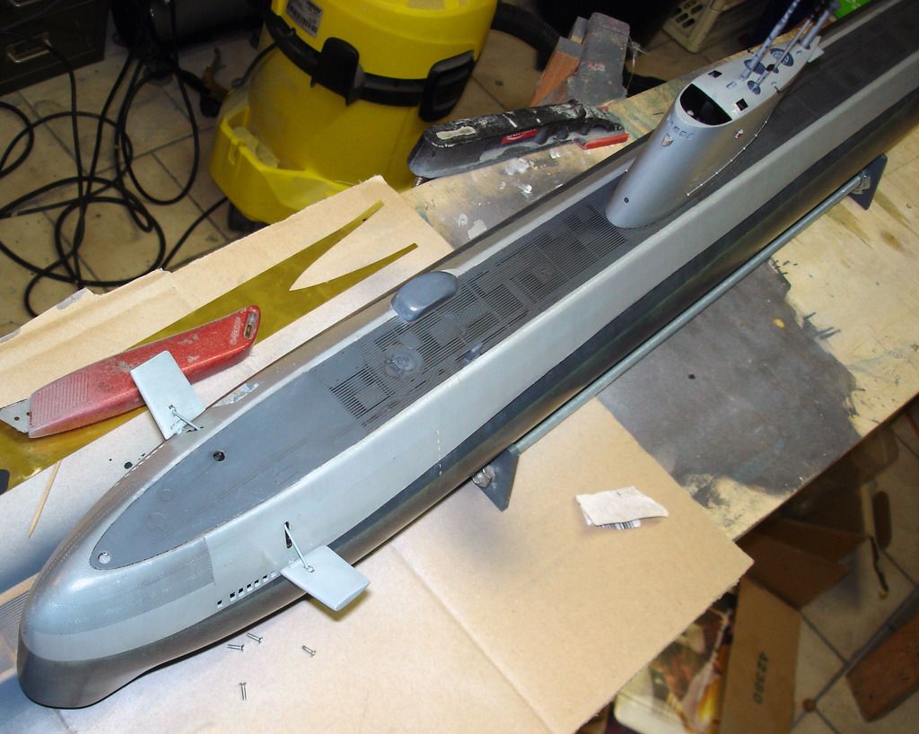
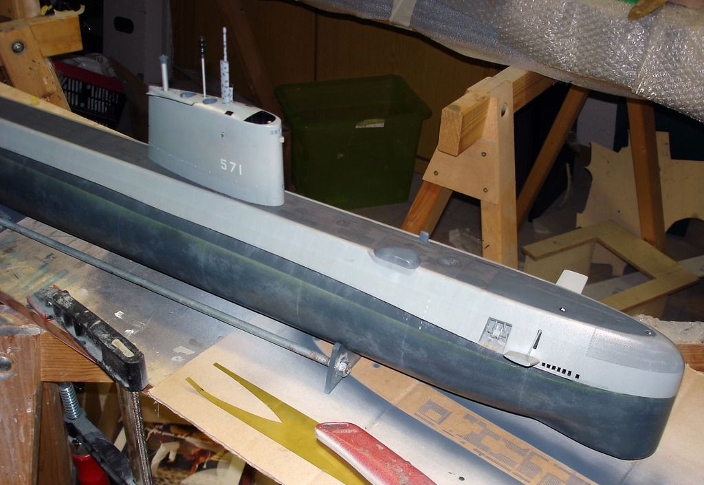
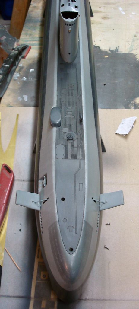
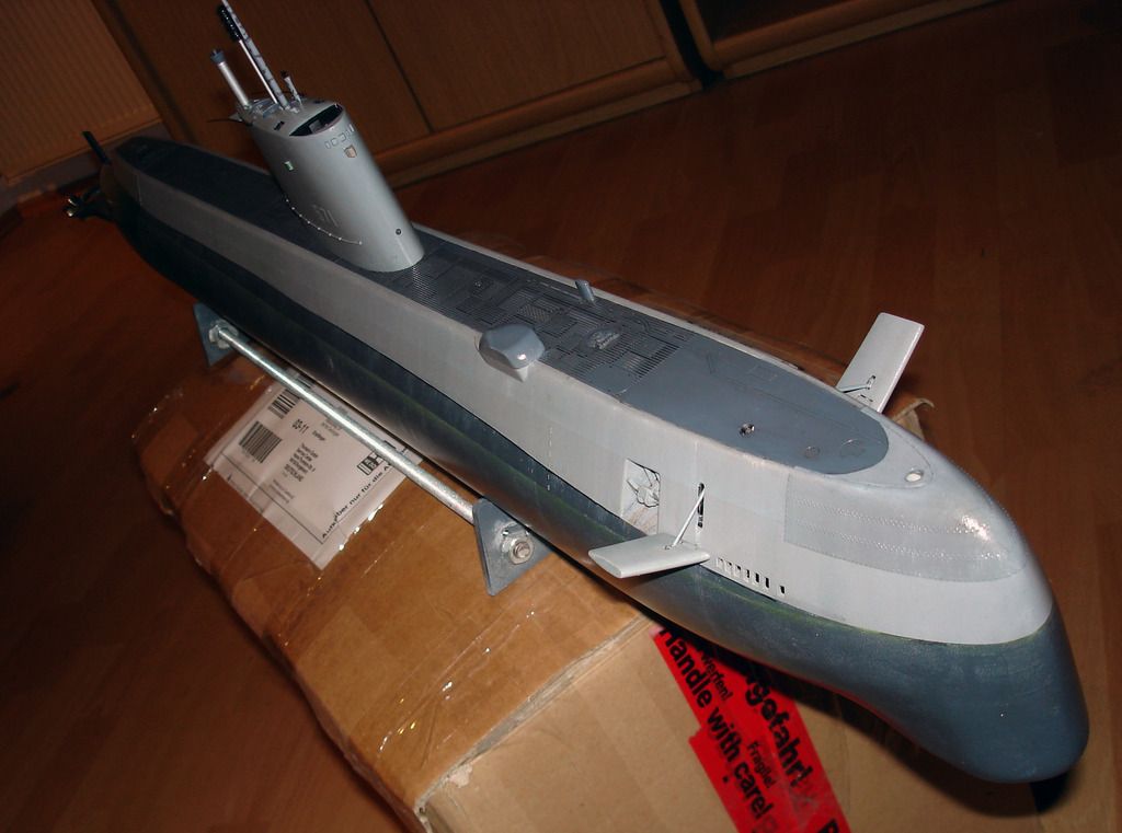
With this picture I'm jumping ahead a bit -- this is Aundrea's initial assembly of his kit. I
include it here to point out the use of the very detailed acid-etched deck pieces.
Provision is made in the upper GRP hull to accommodate this. A slight step is provided
atop the hull to sit this .015" thick acid-etched item atop the hull so that it sits flush.
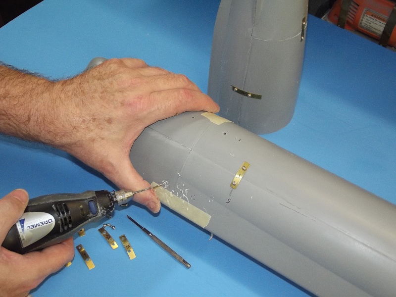
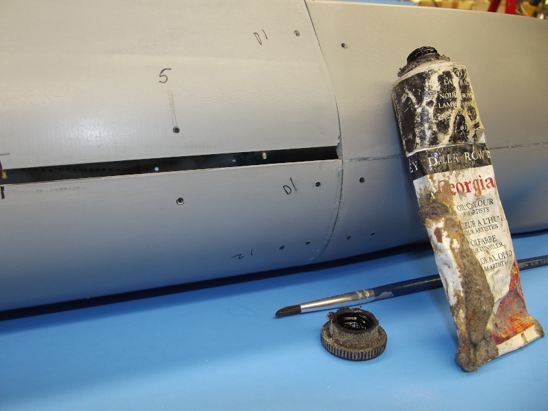
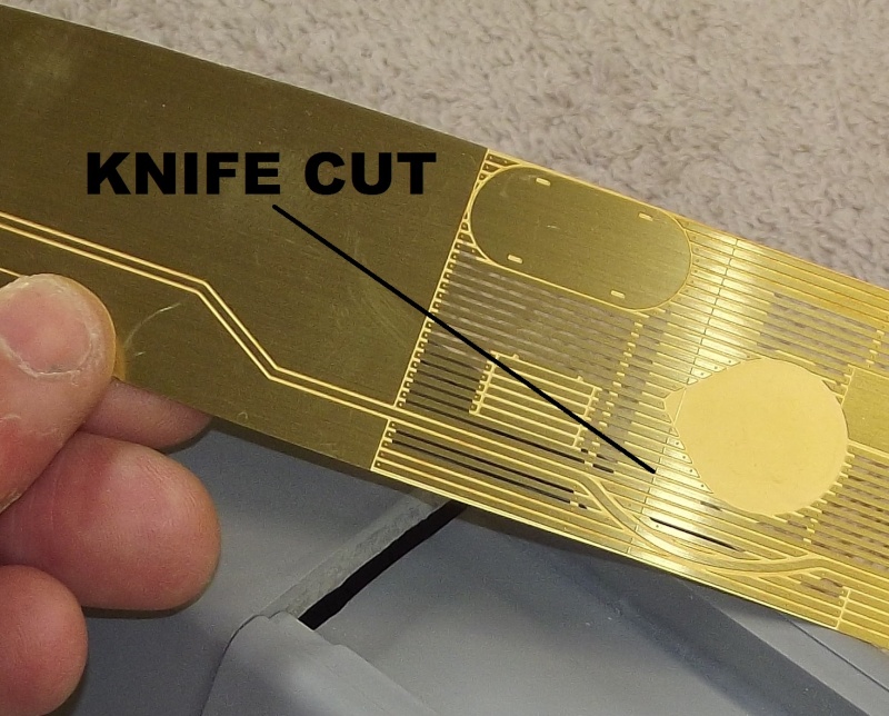
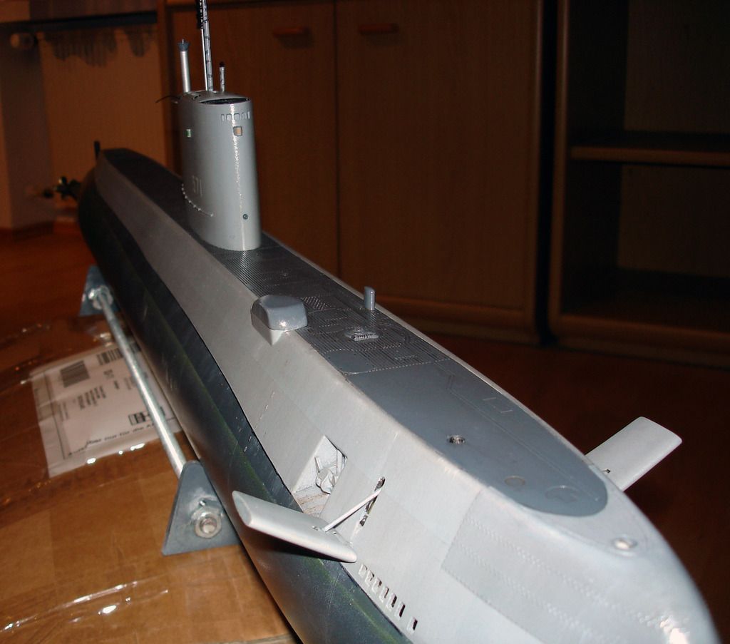
Though the USS NAUTILUS is distinctive of lines, it is a rather boring subject to look at
if the details that are there are not exploited to the maximum -- such is the case with the
deck: safety-track, slotted wooden deck, deck hatches, marker buoys, cleats, torpedo
loading skid, these and more are items captured by the brass metal deck pieces. Even
a bridge deck grating is provided on the acid-etched fret.


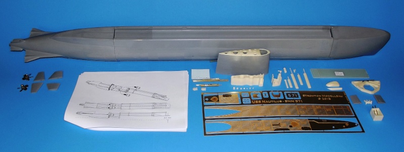
Andreas will be making this kit commercially available. What is pictured above is what I
would consider to be a more than adequate kit: right down to pages of exploded-view,
orthographic and isometric drawings outlining not only assembly of the kit proper, but
recommendations for the fabrication and assembly of the European style internals.
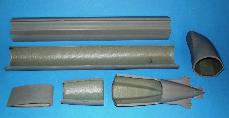
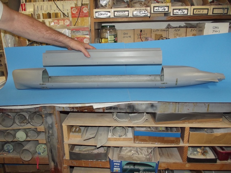
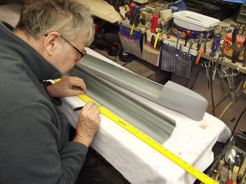
A preliminary kit. What I'm presenting here is likely not the definitive version -- note that
there is no bayonet rings to accomplish the water tight radial break between forward
and after hull halves; that the hull pieces (five of them) are provided split to suit those
wishing to assemble this r/c submarine as either a wet-hull or dry-hull type; and no form
of tech-rack (as the dry-hull guys would describe the internals mounting arrangement)
or water tight cylinder (WTC) is provided. Also, there may be material changes before
the production kits hit the street. So, regard what I've pictured here as a Beta test
article, subject to change.


The resin pieces are of exceptional quality. Right down to the bezels and gyro-repeater
that attach to the open bridge!
The items to the right include the bow plane foundation, anchor well, bow planes
(detailed right down to the universal cup joints that make up to the retract/deploy struts),
deck sonar faring, anchor, and deck hatches. In the middle we see the mast foundation,
open bridge well, sail top with all mast and bridge openings, antenna and snorkel
induction items, as well as the scopes and antennas attached to their respective
fairings. Items to the left are the two rudders and two stern planes.
The dark items are cast from epoxy, the lighter items are cast from polyurethane.


... And these two little jewels: the NAUTILUS propellers! Brass, no less. However, it is
prohibitively expensive to have these propellers cast in brass, so I'm working on
Andreas to consider a white-metal alternative -- any heart-burn about that in the future,
you can blame me. You do want a kit you can afford, right?....
It's obvious Andreas did his homework on these. The blades appear to be of a scale
thickness -- no small feat! And they are of the right shape. These two wheels are simply
gorgeous! Matched with the right motors and gear-train, these propellers should scoot
the NAUTILUS along at a very good clip.


The nominal GRP part thickness is about .050"! In the world of model submarines that is
as good as it can get! And the uniformity of the lay-up is even throughout the parts.
These two observations point to a fabricator who has been grounding in aircraft quality
GRP part fabrication. Which Andrea was. He studied at the feet of an FAI quality
contest r/c powered glider fabricator and flyer. The quality of his glass work is a
testament to this early training. You can't buy that type of training!
Note that the hull kit is presented in five pieces. This break-down offers the customer
the option of assembling this kit either for dry-hull or wet-hull operation. Now, that's
smart tool-design! And greatly increasing the market this project is aimed at.
A dry-hull would demand gluing the two long center hull pieces together, then bonding
the bow to the main hull, and making up a set of bayonet rings to the stern of the main
hull and forward end of the tail section. Access would be the radial break between
bayonet rings.

If configured for a wet-hull -- as I'm doing with the kit Andreas provided me -- you would
bond the forward and after hull pieces only to the bottom main hull piece, leaving the
long upper hull half as the removable element, providing plenty of internal access in
which to mount and set-up a removable WTC (Caswell-Merriman SubDriver in this
example).


An artifact of Andreas' lay-up process are the radial and longitudinal flanges at the
edges of the GRP parts. The flanges are beneficial in that they contribute a great deal of
rigidity to the parts, and offer considerable glue area when bonding adjacent sections of
hull together.
However, in those cases where you want a much stronger bond between the hull parts,
it's best to grind away the flange and to lay in reinforcing strips of glass tape on the
inboard side and saturate the tape with epoxy resin. Part-2 of this article will deal with
that and other kit assembly issues.


The two pieces that make up the stern section of the hull. Here you can see, to better
advantage, the radial and longitudinal flanges at the edges of the two pieces.
The lower pieces is a hatch incorporated in the dry-hull version of the hull -- needed to
access the linkages and running gear in the wet stern section. Not needed on the wethull
version I'm assembling, I bonded the hatch permanently to the after portion of hull.
 

Maistaucher

Vereinsmitglied, Offizieller 1. Avatarbeauftragter
Oops, das sehe ich ja jetzt erst:
Die Bilder sind gar nicht bei RCN hochgeladen. :eek:

Wie traurig wird dieser schöne Bildbericht wohl aussehen,
wenn die Bilder dort auf dem anderen Server irgendwann nicht mehr verfügbar sind? :confused:

Schade. :cry:

bilderlos.jpg
 
Zuletzt bearbeitet:
NAUTILUS PART-2
Part - 2 to this article has got to be the most boring installment to this WIP! No flashy painting techniques. No exotic model building do-dads on display. No combination of kit parts to make this thing look like the eventual USS NAUTILUS.
BORING!
But, what I'm presenting here is a vital phase to the kit assembly task: the gluing together of the separate hull sections; the bonding of the bow to the lower hull main section, and bonding the stern section (itself made up of two separate parts) to the lower hull main section. The desired result will be a removable main hull upper piece that permits access to the models interior -- the huge equatorial spit in the hull making WTC installation and removal an easy and quick task.

About this specific kit: Most manufacturers produce GRP hull pieces that arrive warped out of shape, pieces that demand of you the design and creation of specialized holding fixtures, weird hand contortions, and other means of coaxing the parts into proper alignment as you bond them together.

Not the case with this model! Andreas has produced GRP parts of very, very tight maintenance of original tolerance. Near zero warpage. This model kits GRP hull parts rigidity owed to his incorporation of longitudinal and radial flanges. Those flanges both a blessing and a curse: the flanges kept the GRP parts true of form, yet most of those flanges have to be ground away to permit application of internal layers of reinforcing glass tape and resin as the parts are bonded together.


The end game her e will be the permanent bonding of the bow and stern sections to the lower hull, leaving the upper hull to be removable in order to access the interior of this wet-hull type r/c submarine.


To insure correct alignment of the hull sections to one another I first secured them into a coherent hull assembly with the aid of brass straps, those straps bolted to adjoining hull sections -- three straps per adjoining parts sufficient to insure a secure, non-slipping union. By making the holes in the straps a sloppy fit to the machine screws, enough slop is present to permit adjustment to me made as the parts are brought into symmetric alignment with one another.


First task was to drill and tap holes needed to pass the 2-56 machine screws used to hold the straps tight that pulled together adjacent GRP model parts. Initially I used masking tape and hand pressure to hold a pair of parts together, but only long enough to work out strap placement and where to drill the holes.


Use of a three-foot straight-edge -- placing it to the sides, top, and bottom of the central 'main body' portion of the hull -- was used to check symmetrical alignment between the bow and stern sections to the main body. Loosening the involved straps, repositioning the fit between the sections, and re- tightening the straps was all that is involved to move things around till they are in proper alignment.

To ensure all elements of the hull lined up correctly I included the (eventually) removable upper hull section to the assembly. Once a proper fit between the parts was achieved the upper hull half piece was unstrapped, and the process of bonding the bow and stern pieces to the lower hull begun.


For the moment, the radial and longitudinal flanges are left on all the parts, and the hull sections are strapped together. Once the hull is assembled, the individual straps are identified with a number, that corresponds to the same number printed on the hull. The assembled hull was then taken apart so I could go about the nasty work of grinding off the radial and longitudinal flanges, with the exception of the flanges between main hull halves and the bow and stern part radial flanges that would mate with the upper hull section.


The longitudinal and radial flanges at the edges of all GRP hull parts -- to be joined permanently with epoxy saturated fiberglass strips -- were ground away with moto tools equipped with sanding drum and carbide cut-off wheel. The objective is to present a uniform flat internal surface upon which the reinforcing strips of fiberglass cloth can lay and soak up resin, without the internal 'bump' of a flange getting in the way.

The after hull piece has a 'hatch' which has utility on a radially broken hull, but is useless when you are making a wet-hull with the big upper hull half made removable for access. So, you see the flanges between this after hatch and rest of the stern piece being ground away in preparation of bonding.


In some cases, like this, it's a good idea to remove the straps before getting into the glass bonding chore. The strap screws projected into the hull a bit and would interfere with the lay-up of the fiberglass tape used to lap over the seams between hull parts.

So, to keep things together, I tack glue the hull parts together with CA adhesive, then remove the straps and screws. The machine screws cleared away it was a very simple matter to mix up some laminating epoxy and lay in the fiberglass reinforcing strips within the hull assembly.


Four-ounce weight (fiberglass cloth/matt density is expressed by weight per square yard) cloth tape was cut into inch-and-a-half wide strips. Those strips cut to a length that would girdle, from the inside, one- half the diameter of the hull. These strips, when saturated with resin becoming the reinforcement that would permanently bond adjoining hull sections together.
A neat way of working out developed length of the strips is to use a malleable item, like solder wire, as demonstrated here, to determine the required length of strip needed within the model, then to straighten it out and use that to determine the length of the strips required. Fiberglass matt and cloth is best cut out with a disc-blade knife as seen here. A cutting board of wood works very well, as long as the direction of cut is in line with the grain of the woods surface.


The reinforcing fiberglass tape is laid within the model after first brushing on some catalyzed laminating resin. Note the long handle to the disposable brush here -- it permits easy application of resin to those areas not easily reached by hand.

The many holes used to secure the metal straps were first covered from the outside with pieces of tape. Once resin was laid up within the hull it filled these holes -- the hardened resin restoring the outside of the part ... no more pesky holes to fill and be bothered with later.
 
USS NAUTILUS, PART-3
Unlike most other wet-hull type r/c submarines, this one -- because of the need to achieve an unbroken linkage to the SubDriver (WTC), located in the lower hull, and the bow plan operating and retract linkages, also located in the lower hull -- features a U-cut type break between the two hull halves. With the U-cut both radial breaks occur from centerline up to the top of the hull.
Unfortunately, the U-cut prevents tilting of the upper hull as it's placed down on the lower hull. Where the more familiar Z-cut, with its high radial cut aft and low radial cut forward permits use of a radial capture flange forward, and a single machine screw aft to secure the entire hull assembly -- an assembly that requires angling in the two hull halves during assembly. Not so with a model. making use of right- angle U-cuts.
Presented here is how I worked out the fasteners used to hold the two hull halves together, as well as how 'indexing bolts' (as the German's would describe them) are employed to index the two hull halves tightly together against transverse loads.

dscf8728.jpg


With this type hull separation scheme some means of registering the two hull halves together has to be devised so that they fit together as a tight, non-shifting unit, secured with the minimum number of mechanical fasteners.
I worked out an array of indexting pin-in-hole bolts along the longitudinal flanges of the upper and lower hull pieces to prevent transverse motion of the assembly. I would love to claim authorship to this feature, but ....
... It's a system I stole from Andreas (who produces this kit). He chronicled the use of the pin-in-hole indexing array in this excellent U-1 WIP thread, http://www.modelboatmayhem.co.uk/forum/index.php/topic,52322.0.html?PHPSESSID=a645ffa44d710 9f83a6a4d50934dcc7b
Longitudinal regidity and alaignment was assured by the vertical flanges at the radial edges of the upper and lower hull.
Closure was achieved by a fore and aft machine screw holding the upper hull down upon the lower hull - - that required manufacture and installment of two brass foundation pieces to receive those screws.

dscf9010.jpg


The pin-and-hole indexing array, that would register the longitudinal edges of the upper and lower hull halves together, started by working out an even spacing between the pins and holes along the length of the flanges. This done with Sharpie-pen and ruler.


The pin-and-hole indexing array started with laying out of longitudinal lines. That job best done with a compass: the pen point set high enough to cause the shank of the compass needle to ride along the outer face of the hull as the tool is drawn along, its pen tip inking a line along the length of the flange face.
I elected to install the pins within the flanges of the upper hull half, and the holes to receive the points of those pins drilled into the lower hulls longitudinal flanges.

The compass was adjusted to put the inked line in the center of the flange. As the tool retained its initial setting during the mark-off of the four longitudinal flanges, I was assured uniformity of line-to -hull- surface spacing. close enough for government work. However, as a check, I would later use an old pattern-makers trick to assure a more precise mark-off to assure proper alignment of pin-to-hole.

dscf9018.jpg


The trick is to work one pin-hole pair at a time. Not till a set of pin and hole had been successful achieved, would I move on to the next set.
The process: First, I drill a 1/16" hole into one of the marked spots along the longitudinal flange of the upper hull. A short length of 1/16" diameter brass rod is chucked up into a moto-tool and spun as I filed one end to a blunt point. The pin was then inserted into the hole, pointy end of the pin projecting over the flange face by 3/32".
The next step is to accurately mark onto the lower hull longitudinal flange where the center of this pin goes.

dscf9019.jpg


I applied a very, very small amount of oil paint (black) to the tip of the friction fit pin, then carefully placed the upper hull down onto the lower hull. I kept pushing till the pin makes contact with the lower hulls longitudinal flange -- and kept pushing till the pin was pushed back with its tip flush with the upper hulls flange face. Removing the upper hull revealed a small dot of paint on the lower hulls longitudinal flange where I would drill a hole to pass the pin. That hole slightly larger than 1/16" (.062") -- this to provide a non-interference fit between pin and hole. That bit was a .064" drill. This produces a very tight, non-interference fit between pin and hole.
After removing the upper hull, the pin is pushed to project it's tip 3/32" past the plane of the flange, and CA applied to the inboard side of the flange to affix the pin in place. The two hull halves were assembled to insure a correct fit, then separated and I moved on to the next pin-hole combination. the cycle repeated till the job done.

dscf9020.jpg


The completed pin-in-hole array seen along the longitudinal flanges of the upper and lower hull halves.
The forward screw foundation. Manufactured from 1/2" wide, 3/32" thick brass strip, and bend to a 'Z' shape, is seen here temporarily held within the forward section of lower hull with two 2-56 X 1/4" long machine screws -- these screws eventually removed to clear the way for installation of the eventual forward acid-etched deck piece.

dscf9022.jpg


Two hull closure machine screws, one forward the other aft, eventually secure the upper hull to the lower hull. The two foundations (the forward one seen here) becoming the interface fixtures between the two halves.
(Note the second hole, aft of the other, in the trough of the upper hull. The initial intent was to employ a longer foundation tongue, but that was found to put too much strain on the right-angle bend at the bottom of the foundation piece. With the shorter moment the assembly became a bit more ridged).

dscf9021.jpg


Temporarily attached to the forward portion of lower hull, the forward screw foundation is seen with the upper hull not yet positioned in place. You can see how a securing machine screw would pass through the hole in the trough of the upper hull, pulling it down and onto the foundation, holding the hull halves in place.

dscf9023.jpg


This is the end-game: A solid, ridged foundation upon which the inboard side of the upper hull rests upon. So arranged the upper surfaces of the hull halves match perfectly.
So, with the pin-in-hole array I've forced the longitudinal union between the two hull halves to index tightly against transverse loads; and the two foundations with securing screws pulling the upper hull half down upon the lower hull half.

dscf9110.jpg


The upper hull was removed, the lower hull inverted, and CA applied to the foundation-hull matting surfaces, and when cured hard, the temporary securing screws were removed. Then some laminating resin was catalyzed and reinforcing strips of two-ounce glass cloth laid in to strengthen the foundation bonds.
 
Ah ich denke er wird sie mit einem WTC bauen?

Die meisten Leute in Amiland bauen die Boote als Leerhülle und nutzen dann einen endnehmabren WTC
den man von Boot zu Boot rüber nehmen kann. Problematisch ist das aber wenn man 1 und 2 Schrauben
Boote hat.

Aber FETTEN Respekt für die Arbeit die du dir da gemacht hast. Sieht sehr schön aus! Leider
habe ich nicht die möglichkeiten so viel selber zu machen daher habe ich nur 2 Stangen Boote
von Engel mit dennen ich aber auch sehr zufrieden bin. Wohl kommen noch 2 andere dazu nach dem
was ich auf der Messe gesehen habe.

Freue mich auf die Berichte und wünsche dir alles gute bei deiner Arbeit!

LG Chris
 
Ja, David wird das Boot mit nem WTC bauen. Ich werde wohl auch noch eins mit nem WTC von ihm amchen und vielleicht noc ein Boot mit 1l Kolbentank, um die jetzigen Probleme mit der Wasserlinie zu entschärfen. Tja, und ich lege ein paar Boote zum Verkauf auf.

Das Engel neue Boote rausbringt ist spannen. Ich arbeite auch an einem neuen, kleinerem Projekt:

Rumpf-05_zps3g7fdneb.jpg
 
NAUTILUS PART-4
In this part I'm concentrating on how to handle, cut, and trial position the two acid-etched deck pieces. As I departed from the radial aft break to the hull -- this kit designed as a dry-hull with a single radial break aft employing a watertight bayonet type closure. However, I opted for a wet-hull arrangement which, as the hull kit parts were arranged required two radial backs atop the hull. This change meaning I had to split the forward acid-etched deck piece into two pieces in order to work over the forward radial break.
In addition to outlining the care and feeding of this kits acid-etched deck pieces, I'll also give you some insight into just what the acid-etching process -- more correctly described as, chemical machining -- entails to give you a better idea of the end-products strengths and weaknesses.

THIS is one complete kit: detailed illustrated orthographic and isometric drawings; two beautiful cast brass propellers; GRP sheet marked off to indicate where to cut; bubble free perfectly symmetrical and tight fitting resin pieces; and a complete set of acid-etched parts for the deck, sail bridge, radar reflector, and even a painting stencil used to spray-brush on the large white '571' that goes on each side of the sail.


First step is to part the two deck pieces from the tabs that connect them to the fret. This best done with a sharp knife pressing down onto a firm, un-giving surfaces -- such as a sheet of glass or, in this case, a slab of sheet iron. Place the blade edge perpendicular to the work, where the tab meets the part, and press down firmly. 'Snap'! As the part is cut free of the frets tab.


To insure I made the initial forward brass deck cut exactly over the radial seam at the bow, I laid in the two acid-etched deck pieces -- which indexed perfectly within the shallow trenches of the hull there to fit them flush with the top of the hull -- and only then laid down a straight-edge and made the first light passes with a brand new #11 blade. The forward acid-etched deck piece was removed from the hull, placed on the cutting plate and at least ten light passes of the knife made, using the initial cuts to guide the blade. The piece was flipped and a straight-edge used to guide the blade as that side was scored.


The acid-etched deck pieces are chemically cut from brass sheet. This is flimsy stuff as it is, but after eating away a substantial portion of the material to achieve the high relief and through detailing, the part become exceptionally prone to handling damage.
For this reason, other than using a very thin diamond saw, you should refrain from using traditional sawing tools to part one acid-etched part from another. Instead, as I've illustrated here, you make knife cuts along both faces of the piece; sandwich each half between hard-wood strongbacks; and slightly flex, back-and-forth, the parts at the knife cut till the metal fractures.


In this shot, you can make out the slight recess in the bow that permits the face of the deck piece to mount on the same plane as the GRP hulls deck. Incidentally, the seam between acid-etched deck and hull, not by any accident, is the same demarcation line between the real NAUTILUS hull and deck. This is one accurately engineered and detailed model kit!
Seen to good advantage here is the break in the forward acid-etched deck piece made to accommodate the forward radial break between upper and lower hull halves.


Andreas lavished a great deal of research effort and drawing preparation on his kit. It shows in the highly detailed brass metal deck kit parts. He employed a second-party contractor to produced the acid-etched parts -- that outfit using Andreas' art-work to render the engraved and opened details. The process in professional circles referred to as, two-face 'chemical machining'. Acid-etching to you and me.
The process goes something like this: A piece of brass or stainless steel plate is cleaned and both sides coated with an air-dry photo-sensitive resin. the sensitized metal sheet is sandwiched between two indexed negative/positive film masks. The top mask represented those portions of deck that will be cut all the way through as well as those areas that are to be cut half-way through. The bottom mask represents those portions of the deck that have to be cut all the way through.
Once the photo-sensitive resin is exposed (typically an intense ultra-violet light), the masks are removed, and the sheet agitated within a developer solution that removes/protects the light activated portions of resin. At this point specific portions of the sheet are protected by the resin, the other portions of metal unprotected and now subject to oxidation. The developed sheet is then subjected to either a hot acid or caustic solution soak/impinging spray. Oxidation or corrosion eats away those areas of sheet no longer protected by the resin coating.
Hence the term, 'chemical machining'. And you wind up with the thin metal sheet (the 'fret' in some circles) possessing incredibly defined engraved and open areas. Typically, for economies sake, the fret will contain many different acid-etched model parts and masks -- the items within the fret held in place my tiny tabs, elements of the original art-work.


This little scratch-build model demonstrates the correct selection of materials and fabrication process to suit specific tasks: acid-etched brass sheet to form cockpit detail, markings painting masks, l.g. doors; cast resin parts for small parts of compound curves; and vacuformed polystyrene sheet for large, hollow, low- weight structures of compound curves.


Why do I know so frig'n much about the process of acid-etching? Because I do it myself, in-house.
Like all model building techniques this process has its uses. But, only in specific situations. The talent is knowing what fabrication process to employ for specific parts, and when. Acid-etching employed here to achieve incredibly small, well detailed parts and and painting masks.
Andreas' kits is an example of correct material and process selection -- each type material and process suited to a specific type part: laid up GRP where you need thin-walled items of high strength and of compound curve; cast metal where thin walled strength and natural color is required; and acid etched items where thin-section plate of fine surface detail is desired. The right material and fabrication process for the right job.


The one mystery as to the NAUTILUS detailing not resolved in the kit is the number, placement, and size of the bottom hull ballast tank flood and drain holes, and main seawater suction and discharge holes.
Searching my files I found this excellent Jim Christley drawing showing the as-launched NAUTILUS in profile, both cut-away and external. And it's the upper drawing that revealed a great deal of information on those hull penetrations -- holes I'll have to cut into the lower hull for both scale and functional reasons.
 
part-5
Basic hull assembly done, it came time to address the control surface linkages, running gear, and the removable SubDriver (SD, also known as 'water tight cylinder') foundations. I first replaced the kit provided metric sized control surface operating shafts and propeller shafts with slightly smaller units sized to the imperial system.

... Hey, this is America! We don't do no stik'n metric!
I also took the opportunity to test fit the sail atop the hull as well as checking the fit of the four acid-etched deck pieces.

The primary objective here was to get everything that movies on this model to work correctly from the source, the SD.


The kit provides all the parts and documentation needed to produce a very credible model of the USS NAUTILUS. However, other than the way the hull parts break down, provision of propeller shafts, control surface operating shafts, and perfectly formed and positioned propeller shaft bores (stern tubes), it's the job of the kit assembler to come up with the hardware and devices required to convert the kit .

The control surface linkages, some elements of the running gear, and means of mounting the SD (which contains those control, propulsion, and ballast sub-system elements that must be housed in a dry environment) have to be fabricated or purchased separately by the customer. You see some of that work above in the form of linkages, running gear, and SD mounting hardware.


All three sets of control surfaces (stern planes, rudders, and bow planes) are simple affairs: Each set of control surfaces has a straight run-through operating shaft -- there is no need to provide shaft avoidance yokes, which is the case in most single-shaft designs. The two shafts of the NAUTILUS provide plenty of clearance in the stern for straight-through stern plane and rudder operating shafts -- a desirable situation also made possible by the two sets of operating shafts being well distanced longitudinally.

The cast white metal bell-cranks were at hand: these are parts of my own manufacture, used in our line of plastic model submarine fittings-kits. Each bell-crank secures to a control surface operating shaft with a set-screw. One control surface is permanently glued to one end of its operating shaft while the other is made to be a tight interference fit to the other end of the operating shaft. To install a set of control surfaces the shaft is inserted part way through the hull, and the bell-crank (with pushrod made up through a Z-bend) pushed onto the end of the operating shaft, and the shaft pushed through the opposite hole, and the other control surface pressed into place and twisted into alignment with the other control surface. The bell-crank is then centered onto the shaft and its securing set-screw tightened.


You'll note the use of a large diameter (1/4") aluminum pushrod -- here, made up to the bow plane operating shaft bell-crank. This light weight, yet stiff, pushrod prevents flexing as the control surfaces are positioned against the
load presented by flow forces. Each end of a pushrod terminates in 1/16" brass rod. These rods suitable for make up to the bell-crank through a Z-bend at one end, and a magnetic couplers at the other end of the pushrod. In the above photo you can make out the securing set-screw of the bell-crank which makes it fast to the bow plane operating shaft.

Interfacing the small diameter brass rod and the much larger diameter aluminum tube is an adapter. This adapter made from a sprue of polyurethane resin, bored and turned to integrate the brass and aluminum pieces. The assembly made fast with CA adhesive.


Working out the running gear on this NAUTILUS model is easy: The two beautifully cast and finished brass propellers, and a molded in place propeller shaft bore (stern tube) that runs straight and true through each horizontal stabilizer are provided. All that is required of the kit assembler is to procure and install an un-flanged Oilite bearing at each end of a stern tube; come up with bearing blocks and an astern bearing; and provide intermediate drive shafts that fit between the propeller shafts and SD motor output shaft through universal couplers.

The after Oilite bearing, against which the propeller pushes, serves to transmit the 'ahead' thrust load to the hull. The forward most bearing addressing the backing thrust load through its bearing block which is bonded within the hulls stern.


Beautiful, isn't it? Other than just a little file work to knock down some flash at the perimeter of the appendages, I have not done a thing -- this is how tight and clean the stern is once the parts are assembled. This kit is a marvel of precision, good kit design and manufacture on display!

Into the extreme after end of the stern tubes are set and glued ahead Oilite bearings, against which is a thrust washer, pushed against by the face of the propeller hub.

The GRP stern piece comes to the customer assembled with a perfectly true stern tube through which each propeller shaft passes. As mentioned before, I substituted imperial sized shafts for the kit provided metric. As this undersized those items it was an easy matter to sleeve up the control surface operating shaft openings (which make for simple bearings) to pass the shafts that operated the rudders, stern planes, and bow planes.

At the stern, the only tricky task was to lathe turn the little 1/4" outside diameter intermediate and ahead Oilite bearings. This operation required to make them fit the existing propeller shaft stern tube bore. Stock 1/4" outside diameter astern Oilite bearing were placed in custom made 'astern thrust blocks'.


Looking aft into the hull we see the CA secured astern thrust blocks. Each propeller shafts forward end passes through the astern thrust bearing set within its thrust block. Once installed, the after face of a Dumas type universal coupler presses against a thrust washer which makes contact with the forward face of the astern Oilite bearing. This is where astern loads are presented by the propeller shaft when going astern.

Keep in mind that there are three bearings per shaft:
1. the ahead thrust bearing at the after end of the stern tube, against which the propeller hub (through a thrustwasher) pushes

2. an intermediate journal bearing set at the extreme forward end of the stern tube, to damp out side loads (vibration) the shaft might experience at high RPM's

3. the astern thrust bearing housed within a bearing block which in turn is bonded to the hull

If you look real hard you can just make out the control surface operating shafts and the pushrod bell-cranks that make up to them. In this shot you get an appreciation how easy it is to make up stern control surfaces with a boat that makes use of two, rather than one, propellers.


Center, near the top of the hull are the rudder and stern plane pushrods. At the extreme forward ends are magnetic couplers which make up to their counterparts that run from the after end of the SubDriver, the SD pushrods passing through watertight seals and on into the cylinder were each makes up to a servo.

The magnet of each magnetic coupler makes a press-fit within a resin foundation that, in turn, accepts a threaded rod bonded to its pushrod -- turning the magnet foundation permits fine adjustment of pushrod length.
Between the propeller shafts and the SD motor shafts are intermediate drive shafts. These make up at each end in Dumas type universal couplers. These shafts transmit only torque, no axial loads, so no connectors are needed -- the intermediate drive shafts simply slide into place as the SD is installed within the hull.


This is how the SD integrates within the hull. The SD indexes with the hull through a single brass pin set within the Velcro strap foundation -- this pin, which engages a hole in the bottom of the central ballast tank -- prevents axial and lateral motion of the SD once in place. You can make out the black Velcro strap that securely holds the SD down on the two saddles . The saddles position the cylindrical SD to that its longitudinal centerline falls shares that of the hull.

The removable SD can be installed/removed in seconds. The interface between the hull and SD propulsion, ballast, and control sub-systems are the two propulsion intermediate drive shafts, three magnetically coupled control surface pushrods, and the flexible hose that runs from atop the SD to the sail located snorkel induction mechanism.


A closer look at the saddles and Velcro strap that index and hold the SD within the hull. The strap foundation came from one of the submarine plastic kit r/c conversion fittings kits I produce. The two saddles were cut from laminations of PVC sheet, layered to a thickness of 3/8". The strap foundation was secured with two 2-56 machine screws. The saddles were CA'ed in place after establishing where the bottom flood-drain holes went - I didn't want the saddles to straddle open holes, so I waited till that work was done before determining exactly where in the hull the saddles would go.
Plotting and opening up the flood-drain holes will be covered in the next installment of this WIP.
 
part-6

The flood and drain holes on the bottom of this NAUTILUS model are both an appealing scale feature and a vitally important element in the operation of this wet-hull type r/c submarine.

Through these openings water passes in and out of the hull as the SubDrivers (SD) ballast tank takes on and discharges water. And what better way than through the scale openings in the bottom of the hull? As the kit is primarily designed to be a dry-hull type, there is little in the instructions and no markings on the hull, indicating these flood-drain holes on the bottom of the hull -- it's left for the customer configuring the kit for wet-hull operation to determine the location, size and number of bottom flood-drain holes.

I identified drawings prepared by the much published (and authoritative) Jim Christley That did a pretty good job of identifying the NAUTILUS flood-drain holes. I scaled his drawing up and used them to make a marking template.

Marking the bottom of the hull the location and shape of the flood-drain holes is only part of the task. The GRP hull, essentially silicon glass fibers bound in a hard resin, requires proper tool selection and use to be cut and ground effectively.

The single removable water tight cylinder (WTC), or SubDriver (SD) as I call it, is aligned to the hull through a single indexing pin, and is held down onto two supporting saddles set at the bottom of the lower hull. I'll demonstrate that interface in this installment of the WIP.


There was no molded-in place longitudinal cheat line at the bottom of the GRP hull pieces. No big deal, I determined the dead-center bottom with a piece of radially placed masking tape -- flopping it from being wrapped on one side, then the other and adjusting quarter-radius marks on the tape until I had a radius line on the tape of a length that worked each side of the hull. Using the marked tape as a measuring tool I placed two BDC points on the hull then scribed a longitudinal cheat line, connecting those two points, as illustrated in the above picture -- this engraving became the bottom hull longitudinal datum line off which I radially distanced the flood-drain and main sea water hole locations.


I found a Jim Christley illustration in one of my books that indicated credible locations and approximate lengths of the bottom flood-drain holes -- the ports through which seawater went in and out of the submarines ballast tanks. His drawing also indicated four other very important penetrations in the hull: the two sets of main sea water suctions and discharges.

Though there was no way to garner from this small and slightly smudged illustration the distance the flood-drain holes were from the bottom centerline, I made a best-guess using an old training-aid-book from my submarine days on the WEBSTER. Resolving those documents (and a 1/48 drawing left over from a RTR DeBoer Hulls NAUTILUS job done over a decade ago) to the 1/86 scale of the NAUTILUS model I'm currently assembling, I determined their shape and stand-off distance -- and from that I worked up a flood-drain hole marking stencil from plastic sheet.

A Draftsman's circle stencil was used to mark off the propulsion main sea water suctions and discharges -- one set on each side as the NAUTILUS' hull.


I worked out the ratio between the Christley drawings and the hull, applied that to a set of proportional dividers and lofted the flood-drain hole sizes and distances between centers to a .025" thick piece of polystyrene plastic sheet. The marked off holes then punched out with drill and files to produce a generic flood-hole marking tool. Here you see it put to work marking out some of the ballast tank flood-drain holes in the forward group.


The flood-drain holes were started with the carbide bit -- this tough, very hard coated tool makes quick work of hard substances such as glass. Glass is the 'G' in GRP.

I segregated all my cutting tools into three categories: those for plastic and brass alloys; those for iron and stainless-steel; and those tools condemned to cut GRP. How does a cutting tool get awarded the prestigious honor of chewing on glass? With use and age that tool has become a bit dull, its got one foot in the grave. So, its final use will be heroically grinding away GRP parts. That's how tough GRP is on tool-steel -- once that tool has tasted GRP, it's a gonner.


Over the decades I have assembled quit a collection of files of various shapes, cut, and sizes. here I've selected a square sectioned file to finish off opening the square holes -- holes initially punched out with a moto-tool carbide rasp. See those files? They'll be in a land-fill by this time next year.


The hand-reamer to the left was used to pen up the big circular main sea water openings near the stern. The moto-tool, equipped with a carbide rasp was used to make the initial opening for both circular and square holes; The two square sectioned files were used to give shape to the square holes.

From stencil manufacture, mark-out, to final hole trimming took me the better part of an afternoon. Knowing what tools to assign to the job and how to use them is the key to quick, clean work.


Holding the SD over the lower hull, illustrating the SD securing hardware in the lower hull that secures and indexes it once installed. The white items are the two CA'ed in place PVC plastic saddles. The foundation piece, that both retains the single securing strap, and supports the SD-to-hull indexing pin is in the center. The indexing pin engages a hole in the bottom of the SD's ballast tank, retaining it and keeping the SD from rolling or sliding once the Velcro strap is made up tight.


Demonstrating how the Velcro strap is employed to hold the SD down tightly onto the two mounting saddles. The bottom of the strap runs under and around the strap foundation pieces which in turn is secured to the bottom of the hull with machine screws. The double-sided Velcro (hooks on one side, hoops on the other) is slightly elastic permitting a very tight pull-down of the SD onto the saddles. The strap and the indexing pin makes the SD one with the hull, insuring no pushrod backlash or binding of the running gear.


The thin, very delicate acid-etched deck pieces might become an operational problem. My biggest fear is that some idiot, either launching or retrieving this model, will accidentally push his fat thumb through the very delicate, minimally supported, center acid-etched deck pieces.

To be fair, there are underlying supports for the central acid-etched deck pieces; Andreas has provided transverse GRP cross-bracing upon which portions of the acid-etched deck will sit. The issue is, I don't think there are enough of them -- a lot of flimsy deck remains unsupported.

It's my intention to double the number of below deck braces to give this thing a chance of getting through at least one season of operation without a damaged acid-etched deck!
Contributing to the center deck weakness problem is the incorporation of a trough in the top of the hull.

Why?

Keep in mind that this kit was originally designed as a dry-hull type r/c submarine. The trough was built in to reduce the boats total submerged displacement. Had the kits hull been capped at its deck level (which would have solidly supported the center portions of acid-etched deck) doing so would have resulted in a hull displacing much more water than had the trough been incorporated. More above waterline displacement means a larger ballast tank, and a larger ballast tank takes up more valuable volume within the hull, making installation, adjustment, and replacement of internal devices a Plumber's nightmare.

As it is now the acid-etched deck is divided into four pieces: The forward most piece sits flush at the bow with the entirety of the piece supported by the hull; same with the after most acid-etched piece. The center section, with the trough, has only a few narrow GRP transverse (cross-braces) to support the very flimsy and easily pushed in acid-etched deck. However, the acid-etched deck has narrow transverse solid areas where the actual submarine had these deck re-enforcing cross-braces -- I'll place additional GRP cross braces in the trough, under those solid areas, to add support to the deck pieces over the trough area.
 
Ansicht hell / dunkel umschalten
Oben Unten